Fatigue design
1.0 × 178
160 / 1.1
The fatigue load case is obviously more critical than the ultimate load case.
Note that the highest fatigue class was chosen for the assessment. If the top
flange is considered and the crane rail is fastened to the top flange with bolted
cleats (a more onerous case), the relevant detail category is 90 (description:
structural element with holes subject to bending and axial forces) and the
factored fatigue stress is about 82 MPa. The stress ΔσE,2 must be less than this
value to satisfy the verification equation so a much larger beam is required.
The elastic modulus must at least equal:
NSC 5
Technical Digest 2019
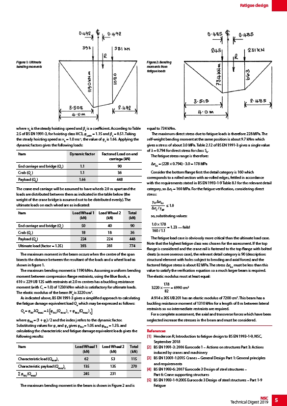
Figure 1: Ultimate
bending moments
where vh is the steady hoisting speed and β2 is a coefficient. According to Table
2.5 of BS EN 1991-3, for hoisting class HC3, φ2,min = 1.15 and β2 = 0.51. Taking
the steady hoisting speed as vh = 1.0 ms-1, the value of φ2 is 1.66. Applying the
dynamic factors gives the following loads:
The crane end carriage will be assumed to have wheels 2.0 m apart and the
loads are distributed between them as indicated in the table below (the
weight of the crane bridge is assumed not to be distributed evenly). The
ultimate loads on each wheel are as indicated:
The maximum moment in the beam occurs when the centre of the span
bisects the distance between the resultant of the loads and a wheel load as
shown in figure 1.
The maximum bending moment is 1190 kNm. Assuming a uniform bending
moment between compression flange restraints, using the Blue Book, a
610 × 229 UB 125 with restraints at 2.0 m centres has a buckling resistance
moment (with C1 = 1.0) of 1230 kNm which is satisfactory for ultimate loads.
The elastic modulus of the beam We is 3220 cm3.
As indicated above, BS EN 1991-3 gives a simplified approach to calculating
the fatigue damage equivalent load Qe which may be expressed as follows:
Q e = fat Qmax,i = fat,1(Qmax,i )1 + fat,2(Qmax,i )2
where φfat,j = (1 + φj ) ⁄ 2 and the index j refers to the dynamic factor.
Substituting values for φ1 and φ2 gives φfat,1= 1.05 and φfat,2 = 1.33. and
calculating the characteristic and fatigue damage equivalent loads gives the
following results:
The maximum bending moment in the beam is shown in Figure 2 and is
equal to 734 kNm.
The maximum direct stress due to fatigue loads is therefore 228 MPa. The
self-weight bending moment at the same position is about 9.7 kNm which
gives a stress of about 3.0 MPa. Table 2.12 of BS EN 1991-3 gives a single value
of λ = 0.794 for direct stress for class S6.
The fatigue stress range is therefore:
ΔσE,2 = (228 × 0.794) - 3.0 = 178 MPa
Consider the bottom flange first: the detail category is 160 which
corresponds to a rolled section with as-rolled edges, fettled in accordance
with the requirements stated in BS EN 1993-1-9 Table 8.1 for the relevant detail
category, so ΔσC = 160 MPa. For the fatigue verification, considering direct
stress:
Ff E,2
1.0
/C Mf
so, substituting values:
= 1.23 — fails!
= 6990 cm
178
82
3220 ×
A 914 x 305 UB 201 has an elastic modulus of 7200 cm3. This beam has a
buckling resistance moment of 1310 kNm for a length of 8 m between lateral
restraints so no intermediate restraints are required.
For a complete assessment, the axial and transverse forces which have been
neglected increase the stresses in the beam and must be considered.
References
1 Henderson R, Introduction to fatigue design to BS EN 1993-1-9, NSC,
September 2018
2 BS EN 1991-3: 2006 Eurocode 1 – Actions on structures Part 3: Actions
induced by cranes and machinery
3 BS EN 13001-1:2015 Cranes – General Design Part 1: General principles
and requirements
4 BS EN 1993-6: 2007 Eurocode 3 Design of steel structures –
Part 6: Crane supporting structures
5 BS EN 1993-1-9:2005 Eurocode 3 Design of steel structures – Part 1-9
Fatigue
Item Dynamic factor Factored Load on end
carriage (kN)
End carriage and bridge (Qc ) 1.1 90
Crab (Qc ) 1.1 36
Payload (Qh ) 1.66 448
Item Load Wheel 1
(kN)
Load Wheel 2
(kN)
Total
(kN)
End carriage and bridge (Qc ) 50 40 90
Crab (Qc ) 18 18 36
Payload (Qh ) 224 224 448
Ultimate load (factor = 1.35) 393 381 774
Item Load Wheel 1
(kN)
Load Wheel 2
(kN)
Total
(kN)
Characteristic load (Qmax,i)1 62 53 115
Characteristic payload (Qmax,i)2 135 135 270
Σ φfat,j (Qmax,i) 245 231
Figure 2: Bending
moments from
fatigue loads