Advisory Desk
The equivalent expression in BR173 is equation (4): f2 = (Nbb – 1)(S/b – 7.5)/25.
The secondary beam spacing should be used in the determination of φ2.
The approach to determining the wind load on unclad structures (lattice
structures, frames and individual members) in SD5 (corrected as indicated)
can also be used with BS EN 1991-1-4 and its UK National annex as the design
pressures have identical target reliability to BS 6399-2.
Contact: Richard Henderson
Tel: 01344 636555
Email: advisory@steel-sci.com
AD 431
Column web panel
strengthening
The purpose of this Advisory Desk note is
to draw attention to the contribution that
full-depth stiffeners make to the shear
resistance of column web panels.
SCI publication P398 covers the design of
moment–resisting connections to Eurocode
3 and provides information on types of
column strengthening in Table 2.1. Within
this table, horizontal stiffeners are not
credited with increasing the shear resistance
of the web panel.
The special case of full depth stiffeners
in both the tension zone and the
compression zone is covered by clause
6.2.6.1(4) of BS EN 1993-1-8. This clause allows
an additional contribution to the web panel shear resistance, based on the
bending resistance of the flanges and the stiffeners which bound the web
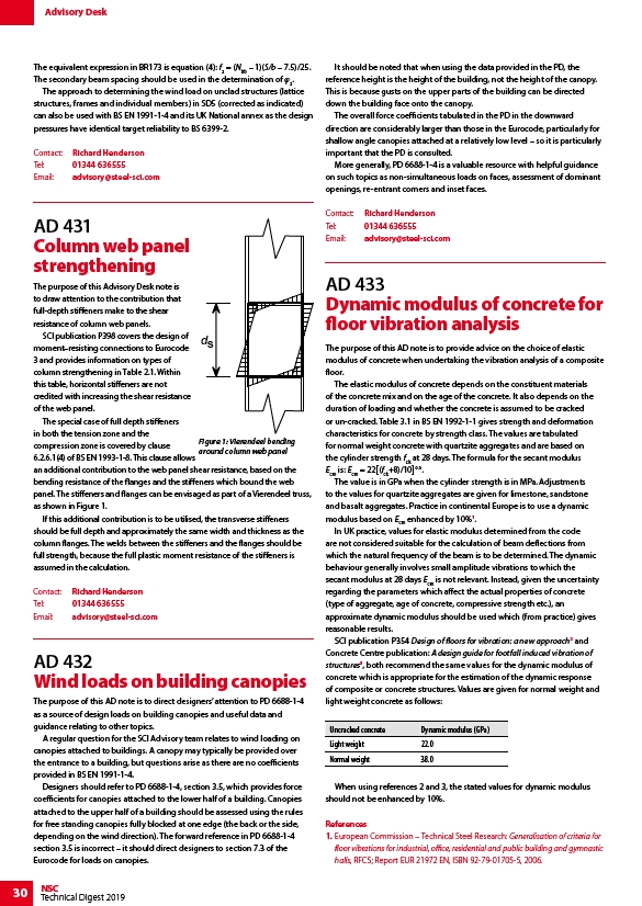
panel. The stiffeners and flanges can be envisaged as part of a Vierendeel truss,
as shown in Figure 1.
If this additional contribution is to be utilised, the transverse stiffeners
should be full depth and approximately the same width and thickness as the
column flanges. The welds between the stiffeners and the flanges should be
full strength, because the full plastic moment resistance of the stiffeners is
assumed in the calculation.
Contact: Richard Henderson
Tel: 01344 636555
Email: advisory@steel-sci.com
30 NSC
Technical Digest 2019
ds
Figure 1: Vierendeel bending
around column web panel
AD 432
Wind loads on building canopies
The purpose of this AD note is to direct designers’ attention to PD 6688-1-4
as a source of design loads on building canopies and useful data and
guidance relating to other topics.
A regular question for the SCI Advisory team relates to wind loading on
canopies attached to buildings. A canopy may typically be provided over
the entrance to a building, but questions arise as there are no coefficients
provided in BS EN 1991-1-4.
Designers should refer to PD 6688-1-4, section 3.5, which provides force
coefficients for canopies attached to the lower half of a building. Canopies
attached to the upper half of a building should be assessed using the rules
for free standing canopies fully blocked at one edge (the back or the side,
depending on the wind direction). The forward reference in PD 6688-1-4
section 3.5 is incorrect – it should direct designers to section 7.3 of the
Eurocode for loads on canopies.
It should be noted that when using the data provided in the PD, the
reference height is the height of the building, not the height of the canopy.
This is because gusts on the upper parts of the building can be directed
down the building face onto the canopy.
The overall force coefficients tabulated in the PD in the downward
direction are considerably larger than those in the Eurocode, particularly for
shallow angle canopies attached at a relatively low level – so it is particularly
important that the PD is consulted.
More generally, PD 6688-1-4 is a valuable resource with helpful guidance
on such topics as non-simultaneous loads on faces, assessment of dominant
openings, re-entrant corners and inset faces.
Contact: Richard Henderson
Tel: 01344 636555
Email: advisory@steel-sci.com
AD 433
Dynamic modulus of concrete for
floor vibration analysis
The purpose of this AD note is to provide advice on the choice of elastic
modulus of concrete when undertaking the vibration analysis of a composite
floor.
The elastic modulus of concrete depends on the constituent materials
of the concrete mix and on the age of the concrete. It also depends on the
duration of loading and whether the concrete is assumed to be cracked
or un-cracked. Table 3.1 in BS EN 1992-1-1 gives strength and deformation
characteristics for concrete by strength class. The values are tabulated
for normal weight concrete with quartzite aggregates and are based on
the cylinder strength fck at 28 days. The formula for the secant modulus
Ecm is: Ecm = 22(fck+8)/100.3.
The value is in GPa when the cylinder strength is in MPa. Adjustments
to the values for quartzite aggregates are given for limestone, sandstone
and basalt aggregates. Practice in continental Europe is to use a dynamic
modulus based on Ecm enhanced by 10%1.
In UK practice, values for elastic modulus determined from the code
are not considered suitable for the calculation of beam deflections from
which the natural frequency of the beam is to be determined. The dynamic
behaviour generally involves small amplitude vibrations to which the
secant modulus at 28 days Ecm is not relevant. Instead, given the uncertainty
regarding the parameters which affect the actual properties of concrete
(type of aggregate, age of concrete, compressive strength etc.), an
approximate dynamic modulus should be used which (from practice) gives
reasonable results.
SCI publication P354 Design of floors for vibration: a new approach2 and
Concrete Centre publication: A design guide for footfall induced vibration of
structures3, both recommend the same values for the dynamic modulus of
concrete which is appropriate for the estimation of the dynamic response
of composite or concrete structures. Values are given for normal weight and
light weight concrete as follows:
Uncracked concrete Dynamic modulus (GPa)
Light weight 22.0
Normal weight 38.0
When using references 2 and 3, the stated values for dynamic modulus
should not be enhanced by 10%.
References
1. European Commission – Technical Steel Research: Generalisation of criteria for
floor vibrations for industrial, office, residential and public building and gymnastic
halls, RFCS; Report EUR 21972 EN, ISBN 92-79-01705-5, 2006.
link
link
link