Fatigue
Fatigue of bracing in buildings
BS5950 states that buildings subject to fluctuating wind loads do not need to be checked for
fatigue but EC3 contains no such statement. Richard Henderson of the SCI considers the issues
and illustrates a fatigue check of wind bracing in a conventional building.
Introduction
Clause 2.4.3 Fatigue in BS5950-1:2000, a code specifically for the design
of steelwork in buildings, states “Fatigue need not be considered unless a
structure or element is subjected to numerous significant fluctuations of
stress. Stress changes due to normal fluctuations in wind load need not
be considered”. The ANSI/AISC 360-16 Specification for structural steel
buildings Chapter B clause 11 states “… Fatigue need not be considered …
for the effects of wind loading on typical lateral force-resisting systems …”.
BS EN 1993-1-1 and BS EN 1993-1-9 (Part 1-9) include no such clause but
BS EN 1993-1-1 forms the foundation for a series of codes for the design
of bridges, towers and other structures. Bridges are routinely checked for
fatigue. Other structures such as chimneys and masts may be subject to
wind-induced oscillations and need to be checked for fatigue.
The connections at the ends of wind bracing are often made using
gusset plates, fillet welded to end plates and beam flanges. Tubular tension/
compression bracing members may have bolted spade-end connections
fillet welded to end plates.
Fatigue Strength Curves
An introduction to fatigue design was published in NSC magazine last year.
Part 1-9 clause 7.1 gives the fatigue strength for nominal stress ranges for a
range of details, identified in Tables 8.1 to 8.10. The fatigue strength is defined
by a (logΔσR) – (logN) curve for each detail category as shown in Figure 1.
For a constant amplitude nominal stress range, the curve gives the number
of cycles to failure or endurance. The curve number is the detail category
and is the constant amplitude nominal stress range that will result in failure
after 2 million cycles. The curves change in slope at N = 5 million cycles. For
nominal stress ranges lower than a certain value known as the cut-off limit
ΔσL , fatigue damage is considered not to occur. The curves are based on the
results of tests on large-scale specimens collected over several decades.
Fatigue damage can be calculated for a given detail using the relevant
18 NSC
Technical Digest 2019
fatigue curve from Part 1-9 to determine the number of cycles to failure Ni for
a given stress range i and using Miner’s summation for fatigue damage Σni/Ni
where ni is the number of occurrences of this stress range over the life of
the structure. The fatigue damage should be less than or equal to 1.0 for the
detail to be acceptable (see Part 1-9, Annex A clause A5). Some fillet welded
details are in the lowest classes of detail identified in Part 1-9 Table 8.5: either
detail category 36* or 40.
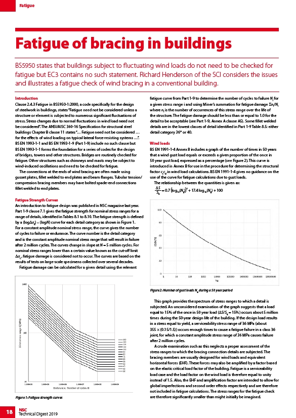
Wind loads
BS EN 1991-1-4 Annex B includes a graph of the number of times in 50 years
that a wind gust load equals or exceeds a given proportion of the once in
50 year gust load, expressed as a percentage (see Figure 2). This curve is
introduced in Annex B for use in the procedure for determining the structural
factor cscd in wind load calculations. BS EN 1991-1-4 gives no guidance on the
use of the curve for fatigue calculations due to gust loads.
The relationship between the quantities is given as:
S
Sk
= 0.7 log( 10(Ng)) 2 + 17.4 log10(Ng) + 100
Figure 2: Number of gust loads Ng during a 50 year period
This graph provides the spectrum of stress ranges to which a detail is
subjected. An unconsidered examination of the graph suggests that a load
equal to 15% of the once in 50 year load (ΔS/Sk = 15%) occurs about 5 million
times during the 50-year design life of the building. If the design load results
in a stress equal to yield, a serviceability stress range of 36 MPa (about
355 × (0.15/1.5)) occurs enough times to cause a fatigue failure in a class 36
joint, for which a constant amplitude stress range of 36 MPa causes failure
after 2 million cycles.
A crude examination such as this neglects a proper assessment of the
stress ranges to which the bracing connection details are subjected. The
bracing members are usually designed for wind loads and equivalent
horizontal forces (EHF). These forces may also be amplified by a factor based
on the elastic critical load factor of the building. Fatigue is a serviceability
load case and the load factor on the wind load is therefore equal to unity
instead of 1.5. Also, the EHF and amplification factor are intended to allow for
global imperfections and second order effects respectively and are therefore
not included in fatigue calculations. The stress ranges for the fatigue check
Figure 1: Fatigue strength curves are therefore significantly smaller than might initially be imagined.