Bolts
Condition Deflection (mm) % increase
No slip 175 -
All members bolted,
470 269
8 mm slip in each joint
350 200
270 55
242 38
NSC 27
Technical Digest 2019
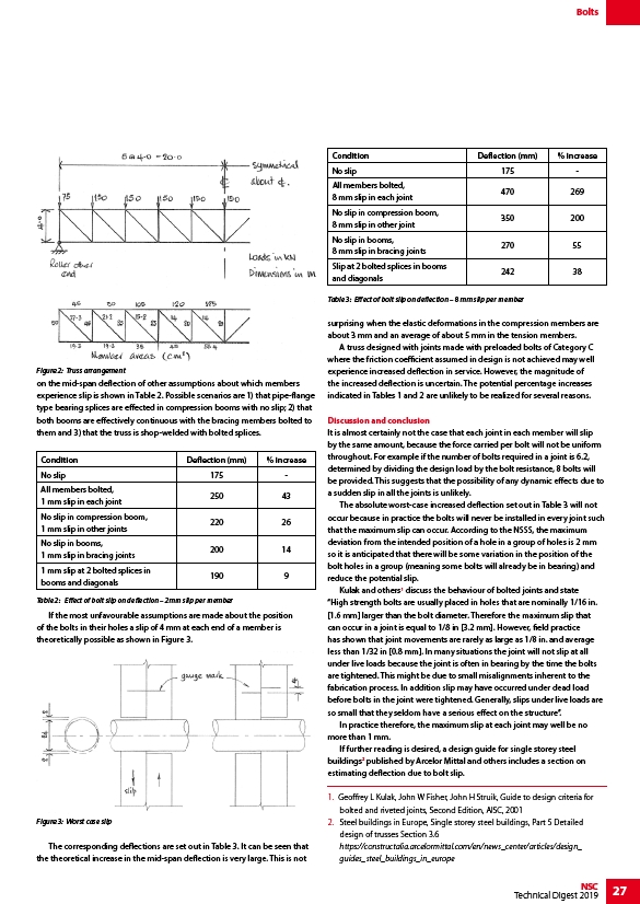
on the mid-span deflection of other assumptions about which members
experience slip is shown in Table 2. Possible scenarios are 1) that pipe-flange
type bearing splices are effected in compression booms with no slip; 2) that
both booms are effectively continuous with the bracing members bolted to
them and 3) that the truss is shop-welded with bolted splices.
Condition Deflection (mm) % increase
No slip 175 -
All members bolted,
250 43
1 mm slip in each joint
No slip in compression boom,
1 mm slip in other joints
220 26
No slip in booms,
1 mm slip in bracing joints
200 14
1 mm slip at 2 bolted splices in
booms and diagonals
190 9
If the most unfavourable assumptions are made about the position
of the bolts in their holes a slip of 4 mm at each end of a member is
theoretically possible as shown in Figure 3.
The corresponding deflections are set out in Table 3. It can be seen that
the theoretical increase in the mid-span deflection is very large. This is not
No slip in compression boom,
8 mm slip in other joint
No slip in booms,
8 mm slip in bracing joints
Slip at 2 bolted splices in booms
and diagonals
surprising when the elastic deformations in the compression members are
about 3 mm and an average of about 5 mm in the tension members.
A truss designed with joints made with preloaded bolts of Category C
where the friction coefficient assumed in design is not achieved may well
experience increased deflection in service. However, the magnitude of
the increased deflection is uncertain. The potential percentage increases
indicated in Tables 1 and 2 are unlikely to be realized for several reasons.
Discussion and conclusion
It is almost certainly not the case that each joint in each member will slip
by the same amount, because the force carried per bolt will not be uniform
throughout. For example if the number of bolts required in a joint is 6.2,
determined by dividing the design load by the bolt resistance, 8 bolts will
be provided. This suggests that the possibility of any dynamic effects due to
a sudden slip in all the joints is unlikely.
The absolute worst-case increased deflection set out in Table 3 will not
occur because in practice the bolts will never be installed in every joint such
that the maximum slip can occur. According to the NSSS, the maximum
deviation from the intended position of a hole in a group of holes is 2 mm
so it is anticipated that there will be some variation in the position of the
bolt holes in a group (meaning some bolts will already be in bearing) and
reduce the potential slip.
Kulak and others1 discuss the behaviour of bolted joints and state
“High strength bolts are usually placed in holes that are nominally 1/16 in.
1.6 mm larger than the bolt diameter. Therefore the maximum slip that
can occur in a joint is equal to 1/8 in 3.2 mm. However, field practice
has shown that joint movements are rarely as large as 1/8 in. and average
less than 1/32 in 0.8 mm. In many situations the joint will not slip at all
under live loads because the joint is often in bearing by the time the bolts
are tightened. This might be due to small misalignments inherent to the
fabrication process. In addition slip may have occurred under dead load
before bolts in the joint were tightened. Generally, slips under live loads are
so small that they seldom have a serious effect on the structure”.
In practice therefore, the maximum slip at each joint may well be no
more than 1 mm.
If further reading is desired, a design guide for single storey steel
buildings2 published by Arcelor Mittal and others includes a section on
estimating deflection due to bolt slip.
1. Geoffrey L Kulak, John W Fisher, John H Struik, Guide to design criteria for
bolted and riveted joints, Second Edition, AISC, 2001
2. Steel buildings in Europe, Single storey steel buildings, Part 5 Detailed
design of trusses Section 3.6
https://constructalia.arcelormittal.com/en/news_center/articles/design_
guides_steel_buildings_in_europe
Figure 2: Truss arrangement
Figure 3: Worst case slip
Table 3: Effect of bolt slip on deflection – 8 mm slip per member
Table 2: Effect of bolt slip on deflection – 2mm slip per member
/design_