Trusses
NSC 25
Technical Digest 2019
them. The webs would need to be checked for shear as well as axial load in
the joint zone. This arrangement is not favoured.
Rotating the members so their flanges are vertical (Figure 4) provides a
more direct path for the flange tension forces.
The connections between the members in the node can be made by butt
welds between the edges of the flanges. The flow of force through the joint
is smoother but the web force still needs to be transferred, and the junction
where the webs of the three members come together is complicated.
A refinement of this arrangement, using two plates to form the node,
separated by intermittent webs is the favoured solution (Figure 5).The plates
toward the centre of the joint are wide enough to carry half the chord force
so a web is only required close to the connecting member to transfer the
web force into the plates. The plates are butt welded to the chord flanges
and the tension diagonal is connected using a bolted splice. The column
member is connected using a bearing splice.
Joint design
The tension splice in the bracing member will be effected using M30
preloaded bolts of category B in double shear, of grade 10.9. The slip
resistance assumed for design is for a friction coefficient μ = 0.5 and is 357 kN.
The member is a 356 UC 340 with 42.9 mm thick flanges and 26.6 mm
thick web and has an area of 433 cm2. The area of one flange is 40% of the
total and carries 5.2 MN in tension. The number of bolts required is indicated
in Table 2:
Force (MN) No of Bolts Adopt
Flange 5.2 14.6 16 bolts
Web 2.6 7.3 8 bolts
The flange splice plates are chosen to provide the same area of metal as
the flange with half the area on each side to balance the force on each shear
plane in a bolt. The splice arrangement is shown in Figure 6. All bolts in the
truss will be M30 grade 10.9 preloaded assemblies, category B.
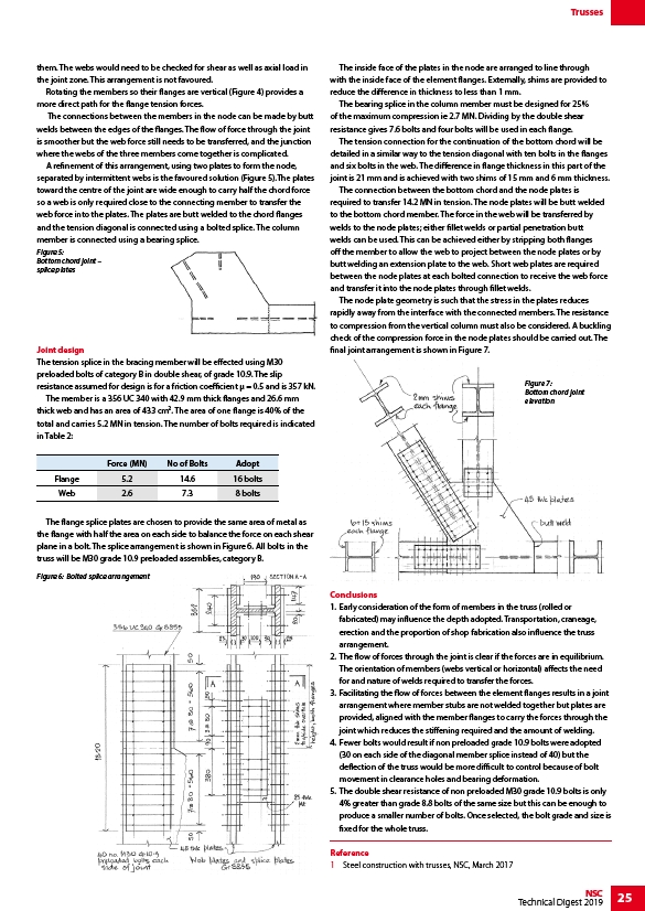
The inside face of the plates in the node are arranged to line through
with the inside face of the element flanges. Externally, shims are provided to
reduce the difference in thickness to less than 1 mm.
The bearing splice in the column member must be designed for 25%
of the maximum compression ie 2.7 MN. Dividing by the double shear
resistance gives 7.6 bolts and four bolts will be used in each flange.
The tension connection for the continuation of the bottom chord will be
detailed in a similar way to the tension diagonal with ten bolts in the flanges
and six bolts in the web. The difference in flange thickness in this part of the
joint is 21 mm and is achieved with two shims of 15 mm and 6 mm thickness.
The connection between the bottom chord and the node plates is
required to transfer 14.2 MN in tension. The node plates will be butt welded
to the bottom chord member. The force in the web will be transferred by
welds to the node plates; either fillet welds or partial penetration butt
welds can be used. This can be achieved either by stripping both flanges
off the member to allow the web to project between the node plates or by
butt welding an extension plate to the web. Short web plates are required
between the node plates at each bolted connection to receive the web force
and transfer it into the node plates through fillet welds.
The node plate geometry is such that the stress in the plates reduces
rapidly away from the interface with the connected members. The resistance
to compression from the vertical column must also be considered. A buckling
check of the compression force in the node plates should be carried out. The
final joint arrangement is shown in Figure 7.
Conclusions
1. Early consideration of the form of members in the truss (rolled or
fabricated) may influence the depth adopted. Transportation, craneage,
erection and the proportion of shop fabrication also influence the truss
arrangement.
2. The flow of forces through the joint is clear if the forces are in equilibrium.
The orientation of members (webs vertical or horizontal) affects the need
for and nature of welds required to transfer the forces.
3. Facilitating the flow of forces between the element flanges results in a joint
arrangement where member stubs are not welded together but plates are
provided, aligned with the member flanges to carry the forces through the
joint which reduces the stiffening required and the amount of welding.
4. Fewer bolts would result if non preloaded grade 10.9 bolts were adopted
(30 on each side of the diagonal member splice instead of 40) but the
deflection of the truss would be more difficult to control because of bolt
movement in clearance holes and bearing deformation.
5. The double shear resistance of non preloaded M30 grade 10.9 bolts is only
4% greater than grade 8.8 bolts of the same size but this can be enough to
produce a smaller number of bolts. Once selected, the bolt grade and size is
fixed for the whole truss.
Reference
1 Steel construction with trusses, NSC, March 2017
Figure 5:
Bottom chord joint –
splice plates
Figure 6: Bolted splice arrangement
Figure 7:
Bottom chord joint
elevation