Stability
NSC 13
h = 10 m;
Columns: 254 UC 107; lz = 5928 cm⁴; Steel: S355 JR
NEd = 75 kN; Example 1.1: H = 20 kN;
Example 1.2: H = 40 kN (factored loads)
EN 1993-1-1 section 5.3.2:
EHF =
Technical Digest 2019
1
200 * 75 = 0.375 kN
Ncr = EIz
(2l)
= 307.16 kN
If the system is represented by a single column:
cr =
Ncr
NEd
307.16
75
= = 4.10
As αcr > 4, local bow imperfections can be
disregarded in the analysis – EN 1993-1-1 5.3.2 (6).
ksw =
1
1-1/cr
=
1
1-1/4.10 = 1.32
Figure 3: Example of a slender simple column.
Worked example Method
leff
m
NEd
kN
H/2 + EHF
kN
First order bending
moment kNm
Second order bending
moment kNm
UF
1.1
2.1 10 75 10.375 103.75 131.29 0.53
2.2 10 75 10.375 103.75 103.75 * 1.32 = 136.95 0.55
3 20 75 10.375 103.75 - 0.63
1.2
2.1 10 75 20.375 203.75 257.77 1.04
2.2 10 75 20.375 203.75 203.75 * 1.32 = 268.95 1.09
3 20 75 20.375 203.75 - 0.96
Table 2: Results for two different load arrangements: simple column13.
Model Bases Beams Columns
Iz
mm⁴
S
m
h1
m
h2
m
h3
m
0.25Ncr,0,AB
kN
1 Pinned
UB 457
191 161
UC 356
406 551
82670 10 3.75 3.00 3.00 30461.02
2 Pinned
UB 457
191 161
UC 356
406 340
46850 10 4.00 3.20 3.20 15172.20
3 Fixed
UB 457
191 161
UC 356
406 235
30990 10 5.00 4.00 4.00 6423.04
4 Fixed
UB 457
191 161
UC 356
368 177
20530 10 5.00 4.00 4.00 4255.08
Vertical loads on each story (unfactored): self-weight; permanent loads: 50 kN/m; imposed loads: 35 kN/m;
Horizontal loads: Example 2.1: H = EHF; Example 2.2: H = EHF + 100 kN (imposed load, unfactored) on each storey;
EHF: Ø = 1⁄200; Column spacing: 10 m; h1 ⁄ h2 = h1 ⁄ h3 = 1.25); Material: S355 JR;
Columns under minor axis bending; Beams under major axis bending; 10 Finite elements per member;
The solution for Model 4 was configured to achieve NEd > 0.25 Ncr,0 (clause 5.3.2 (6) of EN 1993-1-1).
Table 3: Models considered in worked example 2.
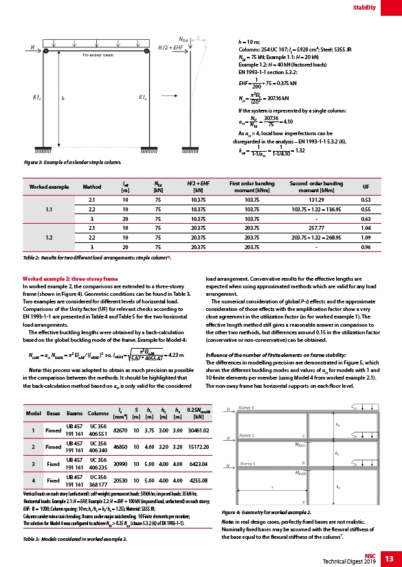
Figure 4: Geometry for worked example 2.
Note: in real design cases, perfectly fixed bases are not realistic.
Nominally fixed bases may be assumed with the flexural stiffness of
the base equal to the flexural stiffness of the column⁷.
Worked example 2: three-storey frame
In worked example 2, the comparisons are extended to a three-storey
frame (shown in Figure 4). Geometric conditions can be found in Table 3.
Two examples are considered for different levels of horizontal load.
Comparisons of the Unity factor (UF) for relevant checks according to
EN 1993-1-1 are presented in Table 4 and Table 5 for the two horizontal
load arrangements.
The effective buckling lengths were obtained by a back-calculation
based on the global buckling mode of the frame. Example for Model 4:
Ncr,AB = αcr NEd,AB = π2 EIz,AB ⁄ (leff,AB )2 so, leff,AB = EIz,AB
5.87 * 4055.47
= 4.23 m
Note: this process was adopted to obtain as much precision as possible
in the comparison between the methods. It should be highlighted that
the back-calculation method based on αcr is only valid for the considered
load arrangement. Conservative results for the effective lengths are
expected when using approximated methods which are valid for any load
arrangement.
The numerical consideration of global P-Δ effects and the approximate
consideration of those effects with the amplification factor show a very
close agreement in the utilization factor (as for worked example 1). The
effective length method still gives a reasonable answer in comparison to
the other two methods, but differences around 0.15 in the utilization factor
(conservative or non-conservative) can be obtained.
Influence of the number of finite elements on frame stability:
The differences in modelling precision are demonstrated in Figure 5, which
shows the different buckling modes and values of αcr for models with 1 and
10 finite elements per member (using Model 4 from worked example 2.1).
The non-sway frame has horizontal supports on each floor level.