Cross bracing
Cross-braced lateral
load-resisting systems
Cross bracing is a traditional means of providing lateral stability to structures.
Richard Henderson of the SCI discusses some of the features of this structural system.
As structural engineers of a certain age will recall from their student days
a cross-braced panel is a statically indeterminate (or hyperstatic) structural
system: the forces in the members cannot be determined simply by
invoking equilibrium at the joints. Determining the forces used to be an
exercise in the application of virtual work to structural problems.
When cross bracing is used to resist lateral loads, the bracing members
are usually designed as tension only and the designer assumes that the
element which forms the compression member buckles elastically as the
frame deforms so as to shorten the relevant diagonal. This approach is
favoured when analysing and designing structures by hand as determining
the buckling resistance of the member is avoided. Crossed flats were
traditionally used for this purpose although angle bracing could be used
so the bracing members had some out of plane stiffness to make handling
easier. Cautionary tales regarding finishes being pushed off by bowing
bracing are told, leading to the adoption of different bracing arrangements.
Flat bar bracing
A flat bar tension only bracing member in a 4 m × 6 m pin-jointed braced
panel (say a 130 mm × 10 mm flat), bolted to the opposing diagonal
member at the centre, has a system length of √13 m, assuming the tension
diagonal provides a point of restraint at the centre connection. (For a
detailed assessment see BS EN 1993-2 Annex D). The out of plane second
moment of area is 1.083 × 10⁴ mm⁴ giving an Euler buckling load:
Ncr = × 210 × 1.0833 × 10
22 NSC
13 × 10
Technical Digest 2019
= 1.73kN
The buckling resistance of the member Nb,Rd is very close to the Euler load
because of the high out of plane slenderness and has a value of 1.69 kN,
assuming S355 material. A compression force of this magnitude is unlikely
to have any effect on a bracing connection designed for a tension force of
450 kN and is usually safely ignored.
An estimate of the bow in the compression member which is making no
contribution to the lateral resistance of the braced panel can be made if the
panel members are known, assuming the member buckles into a circular
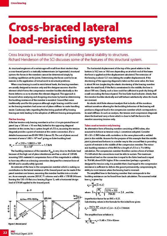
arc. As an example, assume 203 UC 71 columns and a 406 × 178 UB 54 beam
framing the 130 ×10 flat cross bracing (Figure 1), with a horizontal design
load of 374 kN applied to the braced panel.
The horizontal displacement of the top of the panel relative to the
bottom is 16.2 mm or 14.6 mm depending on at which end of the beam
the force is applied and the displacement calculated. The extension of
the bracing is about 12.1 mm (taking the smaller displacement). If the
shortening of the opposing diagonal is taken as the same value, the bow
is about 94 mm (neglecting the elastic shortening of the bracing member
under the axial load). If the flat is unrestrained in the middle, the bow is
about 180 mm. Clearly, such a bow could be sufficient to push dry lining off
a wall concealing the braced panel. The low Euler load indicates clearly that
the member buckles elastically and will behave satisfactorily when the loads
are reversed.
An elastic stick finite element analysis that includes all the members
without somehow allowing for the buckling behaviour of the bracing will
produce a diagonal load in the compression member which corresponds to
its axial stiffness. In such an analysis, the tension and compression diagonals
share the load and carry a force which is close to half the force in the
member assuming tension-only.
Tubes used as tension only bracing
An alternative form of bracing member consisting of RHS tubes, also
assumed to behave as tension-only, is sometimes adopted. Consider
90 × 50 × 5 RHS tubes with centrelines in the same plane with a welded
joint in the middle. Assume for the purpose of this example that the middle
joint is pinned and behaves in a similar way to the crossed flats in providing
a point of restraint in the middle of the compression member. The minor
axis buckling resistance of the RHS for a length of √13 m is 71.6 kN by
calculation. The compression member therefore carries a force of at least
71.6 kN which the connections must be able to sustain. The maximum
theoretical load on the connection is equal to the Euler load and is equal
to 78.4 kN, about 9.5% higher. If the connection (perhaps a gusset) is
designed for tension only, it is possible that a load equal to the compression
resistance is sufficient to deform the gusset permanently, compromising its
ability to resist tension when the bracing load is reversed.
The amplified bow in the bracing member that corresponds to the
buckling resistance can be found from back calculation. The assumed initial
bow e0 is given by:
e0 =
We
A ( –0.2 )
where =
Afy
Ncr
1270 × 355
78420 , and the
= = 2.4
imperfection factor for an RHS = 0.21.
Substituting values in the formula for the initial bow gives:
e0 = 19.7 × 10
1270
× 0.21 × ( 2.4 – 0.2 ) = 7.16mm
The amplified bow at failure is
Ncr
Ncr - Nb,Rd
e0 = 11.48 × 7.16 82mm
Figure 1: Braced panel