Tee sections
The design of tee sections in bending
David Brown of the SCI looks at the lateral torsional buckling resistance of tee sections,
considering the rules in BS 5950 and BS EN 1993-1-1
A tee section? In bending?
A tee section seems an unlikely choice for a member in bending, but judging
by the calls to SCI’s Advisory Desk, designers do wish (or are perhaps required)
to use them. Normally, a tee might be used as a tie between floor beams. The
vertical web fits between floor units and the flange sits just below the units,
making little impact on an uninterrupted soffit. Before hollow section trusses
became popular, tees would have been a good choice for the chords of roof
trusses. The web of the tee (if cut from a UB section) provides enough room to
connect the angle internal members, either by bolting or welding.
This article considers the alternative ways to design a tee section in both
BS 5950 and BS EN 1993-1-1, illustrated with a worked example, so that designers
have a resource if faced with the challenge of an unrestrained tee in bending.
BS 5950 guidance
The verification of a tee is covered in Section B.2.8, which provides rules to
calculate the equivalent slenderness for lateral torsional buckling (LTB). The
first point to note is that guidance is given on when LTB should be considered,
and when not. To avoid confusion with Eurocode terminology, the axis on
the web centreline will be referred to as the minor axis and the perpendicular
axis, the major axis.
In B.2.8.2 a), the Standard advises that if Imajor = Iminor LTB does not occur and
λLT is zero. The same applies to doubly-symmetrical sections where there is no
reason for the section to buckle in the minor axis.
The reverse is true for tees cut from a UB – major axis inertia is larger than
the minor axis inertia and LTB is possible.
Part b) of the clause notes that “if Iminor > Imajor LTB occurs about the major
axis and λLT is given by
20 NSC
:
T2 LT = 2.8( ) ”
Technical Digest 2019
wLeB
0.5
where B is the flange breadth and T
is the flange thickness. Many tees will fall into this category – notably those
cut from UC sections where the web is short and the flange is wide and thick.
A simply supported tee section with Iminor > Imajor , loaded so as to put a short
unrestrained stem in compression will buckle by twisting to reduce the
compression in the stem.
This clause may lead to some significant confusion, because the expression
for λLT for a tee is the same as the equivalent expression for a plate bent about
its major axis, given in clause B.2.7. The expression is based on the St Venant
torsional stiffness of the flange only; the stem of the tee and any warping
stiffness are ignored, hence the similarity with the expression for buckling of
a flat plate.
Finally, part c) of the clause describes when Imajor > Iminor (the common
situation for tees cut from UB) and provides the familiar (for designers of a
certain age!) expression: LT = uv Bw
The clause goes on to provide expressions for the relevant section
properties needed to evaluate λLT , but designers will mostly obtain these from
section property tables. In this case, the warping stiffness of the section is
included in the determination of λLT .
BS EN 1993-1-1 guidance
For tees, there is no change from the normal procedure. To calculate the
non-dimensional slenderness λLT the elastic critical buckling moment, Mcr is
needed. This challenge is conveniently addressed by using software.
Verification methods
In the particular example chosen, the tee is cut from a UB, and thus has a
relatively long web. Classification to either Standard leads to the conclusion
that the tee is slender (BS 5950) or class 4 (BS EN 1993-1-1).
Two approaches are then possible in both Standards. Either the design
stress can be reduced until the section becomes Semi-compact/Class 3, or
an effective section can be determined by neglecting the ineffective parts
of the cross-section. This latter approach becomes more involved in the
Eurocode, because the effective section depends on the stress ratio in the
web, which depends on the position of the neutral axis, which moves as the
effective section reduces – so an iterative process is needed. BS 5950 is more
straightforward as uniform stress in the web is assumed.
Worked example
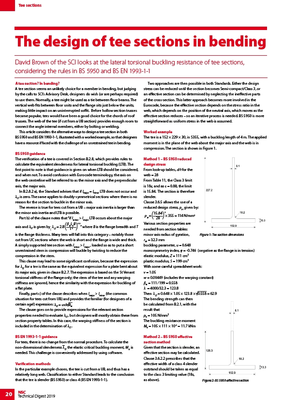
The tee is a 152 × 229 × 30, in S355, with a buckling length of 4 m. The applied
moment is in the plane of the web about the major axis and the web is in
compression. The section is shown in Figure 1.
Method 1 – BS 5950 reduced
design stress
From look-up tables, d/t for the
web = 28
From Table 11, the Class 3 limit
is 18ε, and as ε = 0.88, the limit
is 15.84. The section is therefore
slender.
Clause 3.6.5 allows the use of a
reduced design stress, pyr given by:
15.84
2
p=( ) × 355 = 114 N/mm2 yr 28
Various section properties are
needed from section tables:
minor axis radius of gyration,
Figure 1: Tee section dimensions
ryy = 32.3 mm
buckling parameter, u = 0.648
monosymmetry index, ψ = -0.746 (negative as the flange is in tension)
elastic modulus, Z = 111 cm3
plastic modulus, S = 199 cm3
With some careful spreadsheet work:
v = 1.05
w = 0.00449 (includes the warping constant)
βw = 111 ⁄ 199 = 0.558
λ = 4000/32.3 = 123.8
Then = 0.648 × 1.05 × 123.8 × 0.558 = 62.9
LT The bending strength can then
be calculated from B.2.1, with the
result that
pb = 105 N/mm2
The buckling resistance moment
Mb = 105 × 111 × 10-3 = 11.7 kNm
Method 2 – BS 5950 effective
section method
Given that the section is slender, an
effective section may be calculated.
Clause 3.6.2.2 prescribes that the
effective width of a class 4 slender
outstand should be taken as equal
to the class 3 limiting value (18ε,
as above). Figure 2: BS 5950 effective section