Stability
NSC 11
Stability and second order
effects on steel structures:
Part 2: design according to Eurocode 3
Ricardo Pimentel of the SCI illustrates the different methods provided by EN 1993-1-1 to
address the topics of member stability, global frame stability and second order effects.
Fundamental structural mechanics relating to stability was covered in Part 1.
Technical Digest 2019
Section 5.2 of EN 1993-1-11 introduces an approximate method to calculate
the critical factor of frames (αcr ), based on the well-known Horne method2
(Figure 1). The method is limited to frames with low axial force in the
beams/rafters (NEd ≤ 0.10 Ncr,R ; NEd is the design axial load; Ncr,R is the elastic
critical load for buckling about the major axis of the beam/rafter) and for
frames not steeper than 26°. For other cases, further guidance can be found
in reference 3.
In section 5.2.2 of EN 1993-1-1, different methods are proposed to
consider local (P-δ) and global (P-Δ) second order effects for structural
analysis and member verifications. The following three main methods can
be identified:
Method 1:
Both P-δ and P-Δ effects in addition to local and global imperfections are
directly considered in the global analysis; the deformed structural shape is
considered in the analysis, due to local and global imperfections and local
and global second order effects; second order design internal forces are
calculated. This design method may need to include in-plane and out of
plane flexural buckling in addition to lateral torsional buckling.
Method 2:
P-Δ second order effects and global imperfections are considered in the
structural analysis; P-δ effects are allowed for while performing stability
checks according to EN 1993-1-1 section 6.3; the deformed structural shape
is considered; second order design internal forces are calculated.
Method 3:
Both P-δ and P-Δ effects are accounted for when performing stability
checks according to section 6.3 of EN 1993-1-1. In this method, an
equivalent member length (effective length) needs to be defined. The
allowance for P-Δ effects is made by increasing the P-δ effects by means
of a longer member length. First order internal forces are considered for
the member verification, which may include global imperfections – see
EN1993-1-1 5.3.2 (4). Global imperfections need to be included in the
analysis, generally by applying the Equivalent Horizontal Forces (EHF).
Buckling lengths greater than 2l may be required to allow for P-Δ effects in
structures sensitive to those effects.
For Method 1, different approaches may be taken, as out-of-plane
flexural buckling (FB) and lateral torsional buckling (LTB) may or may not
be relevant. To allow for LTB, according to EN 1993-1-1 section 5.3.4, an
equivalent bow imperfection equal to k∙e0,d may be used, where e0,d is the
equivalent bow imperfection of the weak axis of the profile and k is a
correction factor; it is also stated that in general, torsion imperfections need
not to be considered. According to the UK National Annex4, the value of k is
to be taken as 1. The application of Method 1 is more often used in research,
but several commercial software packages already allow users to directly
consider the P-δ and P-Δ effects within the structural analysis. Method 1,
where local and global imperfection are directly considered in the analysis,
is necessary for the cases where the following condition are met (clause
5.3.2 (6) of EN 1993-1-1):
• αcr < 10, for elastic global analysis;
• At least one moment resisting joint at one member end;
• NEd > 0.25 Ncr,0 , where NEd is the design axial load and Ncr,0 the critical
load assuming a pin-ended strut. This means that for a simple column
system,
cr =
Ncr,o
NEd
< 4
.
Method 2 can be implemented by two possible approaches:
• Method 2.1 - Considering the P-Δ effects directly through a numerical
geometric non-linear global analysis considering global imperfections;
usually computed by commercial software packages; this may
increase the required analysis time for large frames and multiple load
combinations;
• Method 2.2 – Considering the P-Δ effects indirectly by amplifying the first
order sway effects (including global imperfections) by the so-called
amplification factor
ksw =
1
1-1/cr
. As introduced in Part 15, this method is
limited to the cases where αcr ≥ 3. For multi-storey buildings, the rule may
be used when vertical and horizontal loads and frame stiffness are similar
between storeys – see EN 1993-1-1 5.2.2 (6) B.
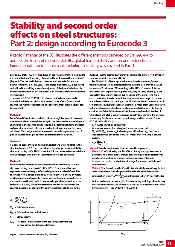
cr =
HEd
VEd ( ) h
H,Ed ( )
HEd – Total storey shear;
VEd – Total vertical load at that storey;
h – Storey height;
δH,Ed – Horizontal displacement of the top storey relative to the
bottom storey due to horizontal loads;
Figure 1 – Horne method to calculated αcr of frames.