Stability
Model αcr ksw
Model αcr ksw
Design
method
MEd,B
kNm
MEd,C
kNm
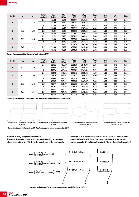
Calculation of αcr using the Horne method:
For model 4 of worked example 2.1, the calculation of αcr according to
clause Section 5.2 of EN 1993-1-1 is shown in Figure 6. The approximate
14 NSC
Technical Digest 2019
Design
method
MEd,B
kNm
MEd,C
kNm
NEd,AB
kN
NEd,AB
kN
NEd,BC
kN
NEd,BC
kN
leff,AB
m
leff,BC
m
UFAB UFBC
1 7.31 1.16
2.1 821.33 453.69 3861.26 2549.73 3.75 3.00 0.48 0.26
2.2 823.99 470.48 3860.86 2549.48 3.75 3.00 0.48 0.27
3 710.34 405.58 3860.81 2549.49 7.79 9.59 0.55 0.36
2 4.41 1.29
2.1 953.98 448.26 3907.42 2585.94 4.00 3.20 0.87 0.41
2.2 972.20 490.65 3906.37 2585.45 4.00 3.20 0.88 0.43
3 753.64 380.35 3906.29 2585.47 7.51 9.23 0.96 0.57
3 8.23 1.14
2.1 482.07 363.31 3990.08 2645.67 5.00 4.00 0.80 0.51
2.2 485.11 375.79 3988.33 2644.74 5.00 4.00 0.81 0.52
3 425.53 329.64 3988.29 2644.74 4.42 5.43 0.75 0.54
4 5.86 1.21
2.1 515.31 357.77 4058.47 2693.69 5.00 4.00 1.09 0.69
2.2 526.53 383.70 4055.75 2692.33 5.00 4.00 1.14 0.71
3 435.14 316.28 4055.70 2692.34 4.23 5.19 0.98 0.71
Table 5: Worked example 2.2: horizontal loads with EHF + 100 kN (imposed load, unfactored)13.
a) Sway frame: 1 Finite element per member:
αcr = 5.94
b) Sway frame: 10 Finite elements per member:
αcr = 5.87
c) Non-sway frame: 1 Finite element per
member: αcr = 41.63
d) Non-sway frame: 10 Finite elements per
member: αcr = 14.81
Figure 5: Influence of the number of finite elements per member on frame stability13.
( )(0.00378)
cr,story 1 = 3 * 12
3 * 2400
= 6.61
5
cr,story 2 =
( 2 * 12
)( )
2 * 2400
0.00587 – 0.00378 = 9.57
4
0.00692 – 0.00587 ( )( )
cr,story 3 = HEd
2400
= 19.04
4
value of 6.61 may be compared with the precise value of 5.87 from Table
4 and 5.86 from Table 5. The approximated value of 6.61 is the same for
worked examples 2.1 and 2.2, as the ratio HEd ⁄ δH,Ed is identical in the method.
H = 12 kN; = 6.92 mm V 2400 kN
H = 12 kN; = 5.87 mm V 2400 kN
H = 12 kN; = 3.78 mm V 2400 kN
Figure 6: Calculation of αcr with the Horne method (worked example 2.1)13.
leff,AB
m
leff,BC
m
UFAB UFBC
1 7.33 1.16
2.1 60.84 33.60 3860.91 2549.80 3.75 3.00 0.21 0.13
2.2 61.04 34.85 3860.53 2549.54 3.75 3.00 0.21 0.13
3 52.62 30.04 3860.53 2549.54 7.78 9.58 0.30 0.24
2 4.42 1.29
2.1 70.66 33.19 3906.91 2585.93 4.00 3.20 0.36 0.21
2.2 72.01 36.34 3906.07 2585.50 4.00 3.20 0.36 0.22
3 55.83 28.17 3906.07 2585.51 7.50 9.22 0.49 0.39
3 8.25 1.14
2.1 35.71 26.90 3989.55 2645.51 5.00 4.00 0.52 0.32
2.2 35.93 27.84 3988.02 2644.78 5.00 4.00 0.52 0.32
3 31.52 24.42 3988.02 2644.78 4.42 5.43 0.49 0.36
4 5.87 1.21
2.1 38.17 26.49 4057.78 2693.40 5.00 4.00 0.64 0.40
2.2 39.00 28.35 4055.47 2692.36 5.00 4.00 0.64 0.40
3 32.23 23.43 4055.47 2692.37 4.23 5.19 0.66 0.49
Table 4: Worked example 2.1: horizontal loads with only EHF13.