Trusses
Connection design in trusses
A general article about steel trusses which touched on choice of members and their
orientation but did not go into detail about designing connections was published in 20171.
In the present article Richard Henderson of the SCI illustrates the implications of such choices
on the connection design.
Introduction
The selection of members and their orientation and the impact on the design
of connections in a truss is best illustrated with an example. The arrangement
of the truss, the magnitude of the forces and the orientation of the members
all have an impact on the form of the connections. A fundamental part of
achieving an efficient joint design is establishing an understanding of the
flow of forces through the joint. This is only possible if the forces provided
for the design of the joint are in equilibrium. If envelope forces are provided,
this compromises the designer’s ability to develop an efficient connection
design. In what follows connections between open section members will be
considered.
As an example, consider a transfer truss spanning 30 m supporting two
columns at third points, each carrying 10 MN from floors above. The truss
is divided into three bays of 10 m width by the columns. The building
storey height is 4.0 m and each floor in the truss will carry a uniform
load of 45 kN/m. The chords are restrained out of plane by floor beams
perpendicular to the plane of the truss.
Truss arrangement
An early decision is what the depth of the truss should be. The maximum
bending moment is 100 MNm from the columns and about 5 MNm from
each floor. If the truss is one storey deep (ie a span to depth ratio of 7.5),
the maximum chord force is 27.5 MN which exceeds the axial resistance of
the largest UC section. In this example, a two-storey truss is chosen, giving
a maximum chord force of about 14.4 MN which can be carried by a UC.
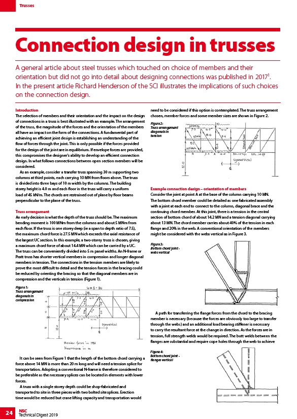
The truss can be conveniently divided into 5 m panel widths. An N-frame or
Pratt truss has shorter vertical members in compression and longer diagonal
members in tension. The connections in the tension members are likely to
prove the most difficult to detail and the tension forces in the bracing could
be reduced by orienting the bracing so that the diagonal members are in
compression and the verticals in tension (Figure 1).
It can be seen from Figure 1 that the length of the bottom chord carrying a
force above 14 MN is more than 20 m long and will need a tension splice for
transportation. Adopting a conventional N-frame is therefore considered to
be preferable as the necessary splices can be located in elements with lower
forces.
A truss with a single storey depth could be shop-fabricated and
transported to site in three pieces with two bolted site splices. Erection
time would be reduced but crane lifting capacity and transportation would
24 NSC
Technical Digest 2019
need to be considered if this option is contemplated. The truss arrangement
chosen, member forces and some member sizes are shown in Figure 2.
Example connection design – orientation of members
Consider the joint at point A at the base of the column carrying 10 MN.
The bottom chord member could be detailed as one fabricated assembly
with a joint at each end to connect to the column, diagonal brace and the
continuing chord member. At this joint, there is a tension in the central
section of bottom chord of about 14.2 MN and a tension diagonal carrying
about 13 MN. The chord member carries about 40% of the tension in each
flange and 20% in the web. A conventional orientation of the members
might be considered with the webs vertical as in Figure 3.
A path for transferring the flange forces from the chord to the bracing
member is necessary (because the forces are obviously too large to transfer
through the webs) and an additional load bearing stiffener is necessary
to carry the resultant force at the change in direction. As the forces are in
tension, full strength welds would be required. The butt welds between the
flanges are substantial and require cope holes through the web to achieve
Figure 1:
Truss arrangement
diagonals in
compression
Figure 2:
Truss arrangement
diagonals in
tension
Figure 3:
Bottom chord joint -
webs vertical
Figure 4:
Bottom chord joint -
flanges vertical