Crane girders
NSC 17
Technical Digest 2019
length by 1.2 (typically), with further adjustment depending on the
support conditions. The equivalent uniform moment factor mLT had to
be taken as 1.0 (so no benefit from the shape of the bending moment
diagram). The Eurocode deals with destabilising loads by adjusting the
calculated value of Mcr , which will lead us to the comment about using
software from a French website.
Calculation of Mcr
The background to the problem of Mcr is that BS 5950 presents bending
strengths pb for different values of slenderness, λLT , which is very
convenient for the designer, as long as one is not interested how the
values have been derived. If interest is sparked, Annex B of BS 5950
provides the background. With patience and algebraic dexterity, one can
demonstrate that the BS 5950 terms depend on a familiar friend – the
elastic critical buckling moment, Mcr . This has been discussed previously4.
Mcr can be calculated using a formula. The version of the formula which
allows for destabilising loads is perfectly amenable to computation by
paper, pencil and calculator as the Verulam correspondence wished.
Software solutions merely make the process easier and, many would say,
less open to error. After extensive experience asking course delegates
to complete a manual calculation of Mcr even without destabilising
loads, the conclusion is that generally over 80% fail to compute the
correct answer. Sadly, the main problem is that delegates attempt to use
inconsistent units within the calculation. Maybe software is safer after all.
The French software mentioned is LTBeam, which has been discussed
several times. Despite the assertion in Verulam, independently written
software from the UK (does that make it better?) exists and is freely
available at steelconstruction.info
If necessary, these two programs could be used for mutual checking,
and then proved by hand calculation – though a spreadsheet is strongly
recommended to remove the tedium of the latter option.
How to check?
The calculation of Mcr is merely a step on the way to the result, so
checking of the final resistance is probably wise. Options are available,
starting with a ‘sense check’ against the results from BS 5950. Since the
introduction of the Eurocodes the consistent message has been that the
structural mechanics has not changed, so one would not expect to find
significant differences in the results obtained by either code. Generally,
the LTB resistance according to the Eurocode is a little higher than
according to BS 5950, so that needs to be recognised, as well as taking
mLT = 1.0 for destabilising loads.
The wise authors of BS 5950 recognised that increasing the effective
length of the member was a good way to allow for destabilising loads.
That simple check can be completed by looking at the calculated member
resistances for the two lengths.
Simple design assessment
Some straightforward checks of the example presented in P385 have
been completed. The example demonstrates the verification of a member
subject to combined major and minor axis bending combined with
torsion, but if the example is reconfigured to assume lateral loads (and
torsional effects due to eccentricity) are taken by a plate welded to the
top flange, the exercise becomes a review of the main member.
The vertical loads are destabilising, so according to EN 1993-6 are
assumed to be applied at the level of the top flange. Accounting for
the position of the loads, Mcr = 320 kNm*, according to P385, and
Mb = 277 kNm*.
The span of the gantry girder is 7.5 m, so applying a factor of 1.2 results
in a span of 9 m. Then one must make a reasonable estimate of the shape
of the bending moment diagram, or conservatively assume that C1 = 1.0
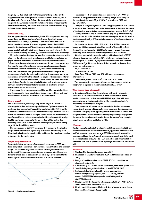
Looking at the bending moment diagram (Figure 3), it looks vaguely
similar to that for a UDL, admittedly with some angularity, but for a quick
check, assume that C1 = 1.13, mainly for easy use of the look-up tables in
the Blue Book.
For the trial section of a 533 × 210 × 101 UB in S275 (note that all
beams are S355 nowadays!), a buckling length of 9 m and C1 = 1.13,
the buckling resistance Mb = 288 kNm. As a coarse check, this is quite
reassuring when compared to the computed value of 277 kNm*.
A further approach is to use the look-up tables in the back of P3625,
where χLT depends only on h/tf and L/iz, which more mature designers
will recognise as D/t and L/ryy in previous nomenclature. The tables in
P362 assume C1 = 1.0, so are likely to deliver a smaller resistance than
computed with precision.
h/tf = 536.7/17.4 = 31
L/iz = 9000/45.7 = 196
Using Table E2 from P362, χLT = 0.38 with some approximate
interpolation.
Therefore Mb = 0.38 × 2610 × 103 × 265 × 10-6 = 262 kNm
This seems to offer reassurance that we are in the correct parish, at
least, when compared to the computed value of 277 kNm*.
What has not been addressed!
In the opinion of the author, the challenge with gantry girders is
not in fact the member verification, but the determination of the
applied actions in accordance with EN 1991-3, a problem which was
not mentioned in Verulam. A treatise on the subject is available for
download6, but the topic is complex.
Other issues not addressed here are the deflection limits for crane
supporting structures, which may be more important than the member
resistance. Designing the supporting structure to control the spread of
the gantry beams will be important. Finally, fatigue design may govern
the size of the member – an introduction to the subject7 and example
calculations8 have been published in NSC.
*Footnote
Readers trying to replicate the calculation of Mcr as quoted in P385 may
have some difficulty. The correct value of Mcr appears to be between 336
and 340 kNm and consequently Mb = 288 kNm. Although it would be
tempting to blame the software, it appears the user calculated the level
of load application as 533/2 + 65 = 331 mm, when 286 mm should have
been used (the load is applied at the top flange, not on top of the 65 mm
rail).
References
1 Verulam, The Structural Engineer, March 2019
2 Handbook of Structural Steelwork, BCSA and SCI (second edition of
1991)
3 Design of steel beams in torsion, (P385) SCI, 2011. Available on
steelconstruction.info
4 A brief history of LTB, New Steel Construction, February & March 2016
5 Steel Building Design: Concise Eurocodes (P362) SCI, 2017
6 Sedlacek et al Actions induced by cranes and machinery
https://estudijas.llu.lv/pluginfile.php/127337/mod_resource/
content/1/20100609%20Exemple-Aachen%20Piraprez%20
Eug%C3%A8ne.pdf
7 Henderson, R. Introduction to fatigue design to BS EN 1993-1-9. New
Steel Construction, September 2018
8 Henderson, R. Illustration of fatigue design of a crane runway beam.
New Steel Construction, January 2019
Figure 3 Bending moment diagram
/