Projects and Features
Restraints around portal frames
In this second technical article on portal frames, David Brown of the Steel Construction Institute reviews the all-important correct positioning and arrangement of restraints to the inside flanges of columns and rafters. Having considered in-plane buckling in the previous article, the focus is now on controlling out-of-plane buckling.
The problem(s) identified
Charles King, well-known to many in the portal frame world and responsible for much of the guidance on this popular form of construction, used to comment when leading SCI courses that some errors in the analysis and design of a portal frame may not lead to collapse, but incorrect detailing almost certainly would. It is clear from inspecting some bare frames during erection and from questions received at the SCI that some designers remain uncertain about where restraints should be located, and what form an effective restraint might take.
Fundamental Physics
The bending moment diagram around a portal frame due to primarily “gravity loads” is well known, shown in Figure 1. At various locations, notably the column and around the haunch in the rafter, the inside flange is in compression under this combination of actions. Elements in compression wish to buckle, and eventually, if unrestrained, will buckle in the out-of-plane direction. The moment is greatest at the eaves – consequently the compression in the inner flange is at a maximum, resulting in great enthusiasm to buckle out-of-plane – which must be restrained if the frame is to remain stable.
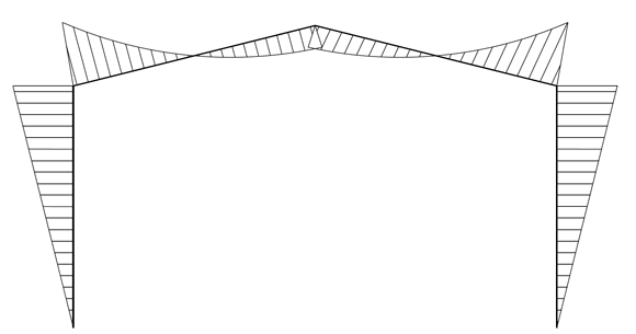 Figure 1: Being moment diagram – “gravity” combination of actions
The classic assumption about members is that they have “fork” supports, as shown in Figure 2.
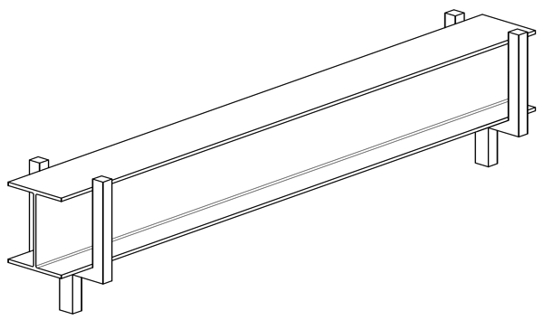 Figure 2: End fork supports – a torsional restraint
It should be noted that a “fork” support provides lateral positional restraint to each flange, thus forming a torsional restraint. It should be equally obvious that a restraint to one flange only, as shown in Figure 3a, is not providing a torsional restraint at that location.
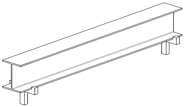 Figure 3a: Lateral restraint to one flange only
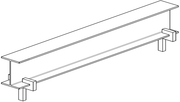 Figure 3b: Lateral and torsional restraint to one flange only
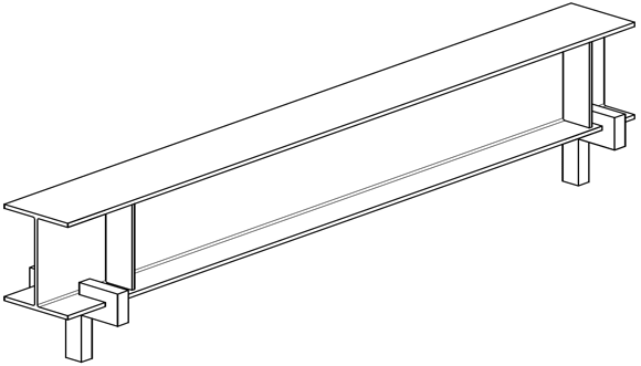 Figure 3c: Lateral and torsional restraint to one flange with web stiffeners
Some arrangement to “clamp” the one flange, as shown schematically in Figure 3b, is still not a torsional restraint, as the unattached flange is free to buckle. An arrangement with stiffeners to connect the flanges together, and a “clamped” flange, as shown schematically in Figure 3c is the only way to provide restraint to the “other” flange, but note the requirement for both stiffeners and a “clamped” flange.
These schematic diagrams illustrate the sorts of questions – and answers – which arise concerning restraints around portal frames. In summary:
- A side rail or purlin connected to one flange only provides lateral restraint to that flange only, but does nothing of value for the other flange.
- Introducing full depth stiffeners in isolation does nothing to prevent lateral-torsional buckling – the whole cross section is still able to move laterally and twist. In this situation the AISC (American equivalent of SCI) note that “transverse stiffeners are simply along for the ride”
- Introducing stiffeners on their own, even when aligned with a side rail, does not constitute a torsional restraint, as the connection to the side rail or purlin is in no way equivalent to the “clamp” shown in Figure 3c. Bolts in clearance holes in very thin material cannot be considered to provide a rigid joint.
In the UK, the common way to restrain the inside flange is to provide small diagonal links from the inside flange to the side rail or purlin, as shown in Figure 4.
 Figure 4: Stays from secondary steelwork to inner flange
Conceptually, this triangulated system is equivalent to the web stiffeners shown in Figure 3c and the secondary steelwork provides lateral restraint. The necessary torsional restraint, equivalent to the “clamping” described above, is delivered by the stiffness of the secondary members acting as “U-frames” as shown in Figure 5.
 Figure 5: U-frame behaviour with secondary steelwork
U-frame action and its application to portal frames was discussed at length in New Steel Construction in June 2018.¹ This article included advice on when and how the stiffness of the secondary steelwork forming the U-frames should be assessed.
The small diagonal ties shown in Figure 4 are normally designed for a lateral force equal to 2.5% of the compression force in the flange, but their stiffness is equally important. If out-of-plane buckling is prevented in the first place, there is no lateral force. Since in the UK we believe that U-frame action is the underlying structural mechanics, we do not believe that the restraint forces translate into tension and compression in the side rails or purlins, nor do we insist that to be effective as part of a restraint system, the side rails and purlins must intersect with the nodes of bracing. Some other European countries make this a requirement. The secondary members must be continuous, otherwise there is no U-frame. Side rails interrupted by roller shutter doors, for example, are clearly not forming a “U” with the adjacent frame.
It is self-evident that a purlin or side rail must be located at the position where a restraint is needed, which means that judicious positioning of secondary steelwork is required, to suit both the cladding and the out-of-plane restraint to the members.
Figure 6 shows a frame during construction. The judicious spacing of purlins is evident – closer spacing in zones of high bending moment and more widely spaced purlins elsewhere.
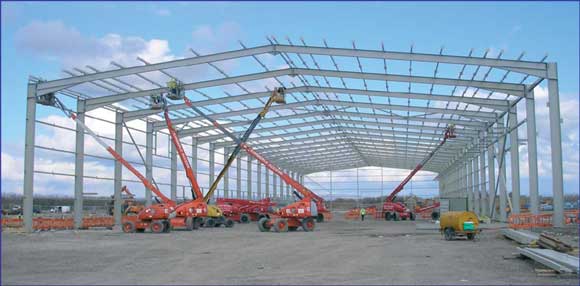 Figure 6: Portal frame with thoughtfully spaced purlins
An alternative approach often used at the most heavily loaded location – where the underside of the haunch meets the column flange – is to position a member at this level, immediately adjacent to the inner flange. It is not adequate to simply tie all frames together at this point, as all the frames could buckle in the same out-of-plane direction. The members at this point must be triangulated back to the outside flange at some point, or connected to the foundation.
Where are restraints needed?
The short answer is wherever the member verification demands. Member verification demands a buckling length, which in the out-of-plane direction depends on the position of the restraints. It is surprisingly difficult to find this fundamental requirement in the Eurocode. Clause 6.3.3 which covers combined bending and axial compression and is therefore applicable to members in portal frames points out in Note 1 that “the interaction formulae are based on the modelling of simply supported single span members with end fork conditions….”. As shown in Figure 2, end forks provide a torsional restraint.
During the recent SCI webinars on the design of portal frames, most discussion centred on the restraint where the underside of the haunch meets the column flange, generally referred to as “Point A”. Horne and Ajmani, who were responsible in the 1970s for much of the research relating to portal frames which we see in BS 5950 and now repeated in the Eurocodes, described this important location as “Point A” and the description has remained ever since.
A number of designers were not convinced that a restraint was essential at “Point A”. It can be inconvenient, because if the cladding is supported at the top of the column, the next side rail down could usually be far below “Point A” if support to the cladding was the only requirement. However, there is nowhere around the frame where the compressive force in the flange is higher, so nowhere more deserving of an effective restraint. A side rail positioned for that purpose (if that system is adopted) is not an expensive and unnecessary addition, but an essential contribution to prevent collapse.
Some designers suggested that with a restraint to the inner flange some way down the column, and another restraint some way along the haunch, the situation would be adequate. The SCI response is to ask which clause is being used to verify the member – which is partly tapered and includes a change of direction of usually 84°. There are no clauses that cover a member with a nearly right-angle kink within the length.
The second common question recognised that there is very often a compression stiffener in the column at “Point A”, and suggested that this combined with a side rail would restrain the inner flange. However, as explained above, a connection in the very thin material of the side rail with ordinary bolts in clearance holes is hardly the “clamp” necessary for this system to be effective.
Designers using bespoke software for portal frame design should make sure they are entirely clear what type of restraint (one flange only, or torsional, demanding restraint to both flanges) they have modelled. “Point A” will invariably be modelled in software with a torsional restraint, which must be provided in the physical structure.
Figure 7 should serve as a dramatic warning. No restraint at “Point A” has simply allowed the point to buckle laterally. This should not be allowed to happen – and yet – it is sometimes possible to see buildings under construction without this point restrained. It is also possible to see structures where the restraints have been detailed and provided to the bottom flange of the rafter, rather than the bottom flange of the haunch. At the deep end of the haunch, we would expect the compression to be in the bottom flange of the haunch and this location should be restrained. The bottom flange of the rafter, being approximately on the neutral axis of the compound section, should have hardly any force at all.
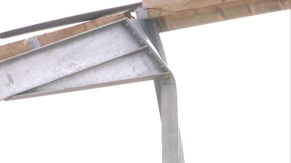 Figure 7: The result when Point A is not restrained
Conclusions
The importance of restraints to the compression flange (the location of which will vary in different combinations of actions) cannot be over-emphasised. Such restraints are fundamental to the structural stability of the frame, and omission could lead to collapse. Restraints to the inner flange must be identified, specified and provided in the actual structure.
1 U-frames in bridges
New Steel Construction, June 2018


