Projects and Features
Going big in Avonmouth
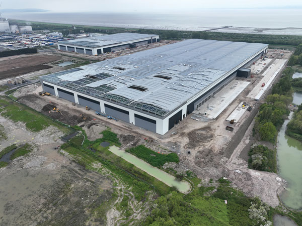
Comprising two distribution centres, structural steelwork has been completed on the UK’s largest-ever speculative development.
FACT FILE
Panattoni Park, Avonmouth
Main client: Panattoni
Architect: AJA Architects
Main contractor: ISG
Structural engineer: Hydrock CDP
Steelwork contractor: Severfield
Steel tonnage: 4,900t
The construction of vast distribution centres shows little sign of slowing down, as a raft of projects are currently underway across the UK, with many more about to kick-off later this year.
With nearby major international docks and rail freight facilities, as well as being close to both the M4 and M5 motorways, Avonmouth near Bristol has become one of the prime locations for distribution centres.
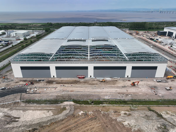
A short distance from the River Severn, developer Panattoni is currently constructing the UK’s largest-ever speculative development in order to supply what is said to be an under-supplied market. The scheme, known as Panattoni Park, Avonmouth, consists of two 17m-high units; one offering 37,718m² of floorspace and a much larger unit providing 82,727m².
Sustainability is at the heart of the project as both units are aiming to achieve a BREEAM ‘Excellent’ rating and an EPC rating of ‘A’. They will also benefit from sustainability features such as roof-mounted solar PVs, rooflights and EV charging points.
As part of Panattoni’s net zero programme, Avonmouth is the latest development to be targeting net zero for embodied carbon during construction, by enhancing a number of sustainable credentials.
One of these measures is the use of an analytics system, which helps the company monitor the fuel consumption required for its site cabins. By rationalising and turning off power in unused rooms, it enabled the downsizing of the required generator, thereby making some considerable cost and fuel savings.
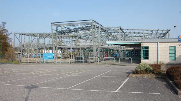
Work on the brownfield site, which was previously occupied by an ICI facility, began in 2018. Drainage and flood defences were formed in anticipation of a groundworks and profiling package that included a large-scale remediation programme.
Prior to the two building’s steel frames being erected, over 14,000 × 250mm-diameter driven piles were installed to a maximum depth of 14m.
The piled foundations support the unit’s ground floor slabs, as well as the structure’s steel frame, as each column, which are spaced at 3.3m intervals, is founded on four individual piles.
Working on a design and build contract, steelwork contractor, Severfield, says a sustainable approach has been undertaken, so that all of the steel sections used for the project are as efficient as possible.
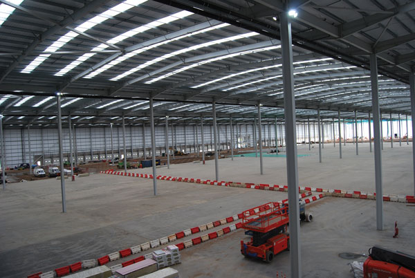
Once the site was ready, Severfield began its erection programme with the larger Unit 2. This portal–framed building is 425m-long (53 bays) × 188m-wide and comprises five 37.6m-wide spans.
Predominantly using three mobile cranes for the erection of each building, both unit’s spans were erected with each rafter being lifted into place in two pieces.
Severfield Operations Director Stephen Jay-Hanmer, says: “Once the rafter’s two pieces have been connected to their supporting columns using two cranes, the central splice is bolted up. A third crane is then used to install infill secondary steelwork, while the other cranes continue to support the main rafter.”
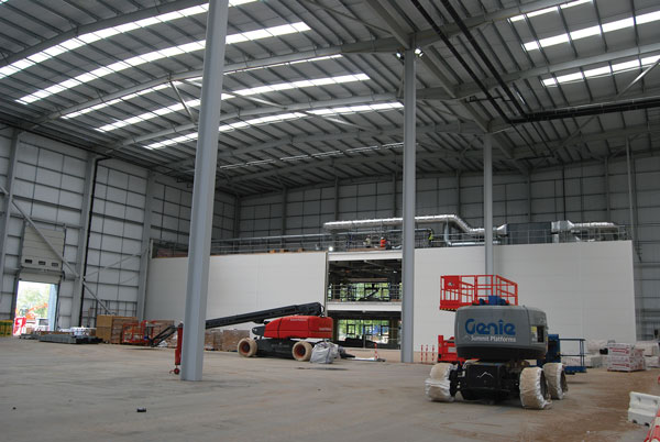
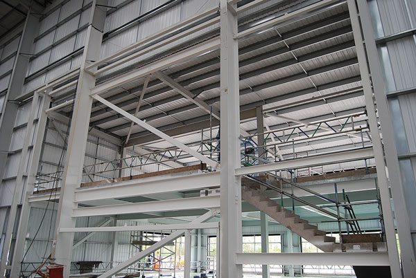
Within its footprint, Unit 2 includes a two-storey office as well as a couple of two-storey hubs. All three of these facilities are formed with steel beams supporting metal decking and a concrete topping for a composite flooring solution. The roof of the office is formed with the same method as it accommodates a plant deck.
The main office is on the project’s critical path as it requires more fit-out than the majority of the building. For this reason, it was one of the first parts of the steel frame to be erected.
Before Severfield had completed the steel frame for Unit 2, the erection programme for Unit 1 had already begun. At this point, there were two separate gangs working simultaneously with a total of six cranes onsite.
“Speed of construction, especially for the steel frames, is vital on projects such as this,” says ISG Project Director Phil Sidell. “A number of other trades follow-on directly behind the steel erectors, so once a few bays are up, the cladding and roofing installation is begun, making the building watertight as quickly as possible.”
The smaller Unit 1, measures 255m-long × 144m-wide and consists of four 36m-wide spans. Similar to its larger neighbour, this building also contains a two-storey office with a rooftop plant deck and a two-storey hub office.
A further steelwork package includes a three-level car park for Unit 2. Positioned at the front of the building, it will provide 693 parking spaces, 10% of which will have EV charging points. Unit 1 will have a similar steel-framed car park, offering 380 spaces over two levels.
Summing up, James Watson, Head of Development, Panattoni said: “It’s great to see such great progress at the site, developing the largest-ever speculative logistics facility in the UK.”
Panattoni Park, Avonmouth is due to complete in September.
Designing for steel erection
The distribution centre at Panattoni Park serves as a reminder that even apparently orthodox forms of construction demand a thoughtful approach when the steelwork is erected. David Brown of the SCI reminds designers of their obligations to consider erection in the design process.
The Panattoni Park, Avonmouth Distribution centre is similar to many others around the UK – multiple spans, hit and miss frames to maximise the column-free space. One notable comment in the main article is that the rafters were lifted separately and the apex splice completed at height – not bolted on the ground. The rafter pair had then to remain on the cranes whilst a third crane was used to erect some of the purlins. Two issues are highlighted here. Firstly, a rafter pair spanning nearly 38 m is a very slender member to attempt to pick up as one unit. In this case, the better solution was to use a crane for each of the individual rafters, but this introduces different risks of completing the apex joint at height.
The second issue is that a rafter pair is unstable until at least some of the purlins are attached – so the rafter pair must remain supported by the cranes until these vital restraints are added. The situation when erecting trusses is another common case – the compression chord will buckle out of plane unless intermediate restraints are added, so the truss must be supported until additional members are erected.
Common practice in the UK is generally to assume these issues of temporary stability are entirely the steelwork contractor’s responsibility, but this is not the case. Designers have an obligation to consider hazards which give rise to risks, and – so far as is reasonably practicable – eliminate or reduce the risks and provide information on the risks that remain to be managed by others.
Although BS EN 1090-2 might be assumed to only cover the responsibilities of steelwork contractors, the standard does place obligations on the designers of structures. Clause 9.3.1 covers the Design basis for the erection method, which is required if the structural stability of the part-erected condition is not evident. Items a) to s) of that clause illustrate the issues to be considered, including requirements for temporary bracing, or propping, and the conditions for removal of such temporary works. The National Structural Steelwork Specification (NSSS) 7th edition presents the same guidance in Table 1.5 and clause 8.4.1 – a further reminder that the designer of the structure should be considering the temporary conditions during erection and providing information on necessary restraints.
Anecdotal evidence suggests that the temporary condition is often not considered at the design stage – so there is “room for improvement”.