Projects and Features
Creative highlights
 A large mixed-use scheme, with office space geared towards the creative industries, will transform a swathe of land on the edge of London’s Soho district, offering a host of amenities including new public realms. Martin Cooper reports.
FACT FILE
Ilona Rose House Development, London
Main client: Soho Estates
Architect: MATT Architecture
Main contractor: Sir Robert McAlpine
Structural engineer: Tier Consult
Steelwork contractor: William Hare
Steel tonnage: 2,900tLocated at 111-119 Charing Cross Road, the plot previously occupied by the famous Foyle’s book shop, Ilona Rose House is a new 27,800m² mixed-use development that will include ground floor shops and restaurants, office space on the upper eight floors including garden terraces, and a four-level basement that will house Warner Brother’s European post-production studios, including a double-height 60-seat editing theatre.
Surrounding the building, a large portion of the site is dedicated to new public realm space with a new café and restaurant-lined mews linking Manette Street to Greek Street. The mews will also provide an entrance to the extensive subterranean creative office and post production space.
Aiming to achieve a BREEAM ‘Excellent’ rating, the scheme also includes redevelopment of 14 Greek Street, a Grade II listed building, which will be protected and carefully restored. Next door, at 12-13 Greek Street, the façade of the building is being retained while eight affordable housing flats are constructed behind it.
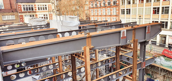
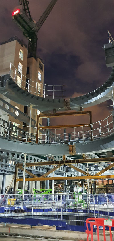
The cantilvering truss, which forms the main elevation, takes shape

A ‘spotlight’ atrium is formed with curved members.

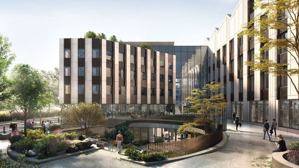
Model showing the main elevation
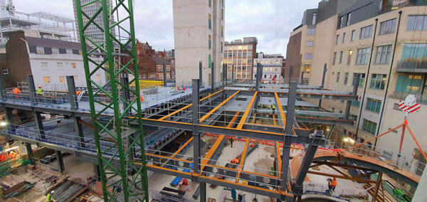
Cellular beams have been used throughout the development to accommodate building services
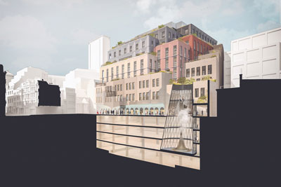
Cut-out model showing the rear of the development and the atrium
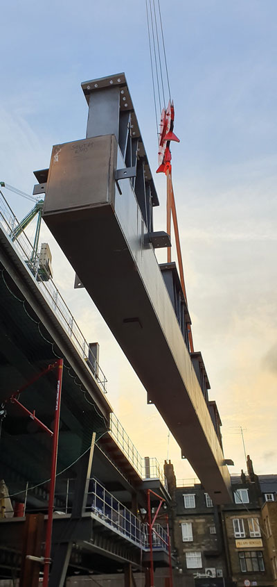
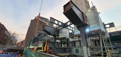
A fabricated plate girder is lifted into place
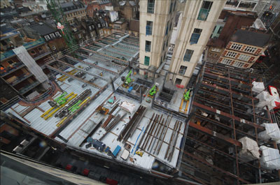
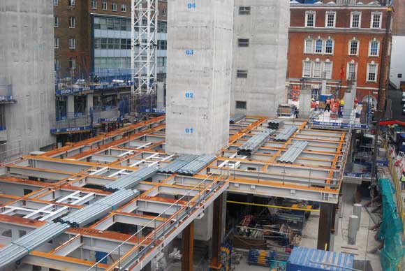
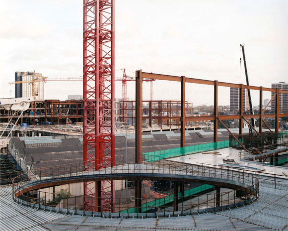
Steelwork is erected around a centrally-positioned concrete core
Each girder was supplied in three sections, red, orange and blue, and welded together onsite, while supported on temporary props – yellow
The main building consists of a steel-frame superstructure, which is erected around a centrally-positioned concrete core.
Cellular steel beams, used to accommodate services within their depth, have been used throughout. The beams are typically 725mm-deep with 500mm-diameter holes at 750mm centres.
From ground floor upwards, the steel beams support metal decking to form a composite flooring solution. Externally, the structure features bespoke precast concrete façade panels, clipped on to a traditional curtain wall system.
Work onsite began last year and following the demolition of the previous building, an extensive groundworks programme was undertaken, which included a deep excavation to enlarge the existing basement to the required four levels.
Once the concrete slab for the deepest basement level four was installed, William Hare was able to begin its steelwork programme as the majority of the steel columns are founded at this level.
The subterranean portion of the building is a hybrid design, with steel columns and beams and the floors formed with concrete. Basement level three has a insitu concrete deck with no steel beams, but levels two and one have steel beams with a concrete slab cast around them.
This method of construction was chosen as the basement will house office space and a similar long span arrangement to the above ground levels was needed.
In the building’s south west corner, a ‘spotlight’ shaped atrium, dramatically cut into the basement, will provide daylight deep into the lower floors which are designed specifically with the film and creative industries in mind.
The circular void atrium is up to 5.8m-diameter and has been formed with a series of 700mm × 700mm × 40mm curved box sections set into the relevant floor slabs.
“The basement had a number of temporary props, which could only be removed once the floors had been installed. We had to erect the columns, which are typically two-storeys high, around the props and then wait until the concrete slabs had been installed before we could erect further columns,” says William Hare Senior Project Manager Richard Mosek.
Above ground, the retail areas and offices are said to exploit the stepped massing of the building to create over 1,100m² of planted external terraces for the benefit of occupants. This means from level three upwards, the building’s footprint gradually decreases.
“The bulk and the massing of the building is biased toward Charing Cross Road, where the general height of the surrounding buildings is greater. The building then cascades down towards Greek Street on its western perimeter,” explains Tier Consult Engineer Jim Fraser.
“The need to reduce the mass on the western side and introducing terraces led to the use of a series of transfer structures to support the changing perimeter column lines.”
Radiating out from the central core, the upper levels feature minimal internal columns and open-plan areas are created with numerous long span beams. The project has 23 beams that span up to 19m or more, with the longest being 19.6m.
According to William Hare Senior Site Manager Ben Burns, the biggest challenge for the steelwork programme is the main Charing Cross Road east elevation. On this side of the building there is a 34m-long × 4.4m-deep cantilevered truss, weighing in excess of 66t, positioned at first-floor level.
“It had to be broken down into sections, no heavier than 16t each, so as not to exceed the lifting capacity of the onsite tower crane. To assemble the sections, we had to use 35t of temporary support steel and do three weeks of continuous 24-hour onsite welding. This included a total of 64 full penetration butt welds with thicknesses of up to 100mm, which is the equivalent of one 5,400m-long weld.”
The cantilevering truss will create a feature overhang above the ground floor retail area. This architectural highlight extends around the corner and along a portion of the Manette Street façade. There are no corner columns positioned at ground floor as they would have been obtrusive to the architectural design and so the truss was introduced as the best option.
With no columns beneath, the truss is effectively hung from the underside of four plate girders positioned at the underside of level two. The girders’ back spans are restrained by the primary beam line on the east side of the core.
The girders are between 15m-long and 18m-long, and weigh in the region of 40t each. They are tapered and have a depth that varies from 730mm to a maximum of 1.5m depth.
As these sections would have also exceeded the lifting capacity of the onsite tower crane, each girder had to be delivered to site in three pieces.
Summing up, Sir Robert McAlpine Project Director Allan Cameron says: “From the outset, William Hare has worked hand-in-hand with Tier Consult to provide the most efficient solution with a key consideration given to buildability.
“With a fully coordinated and integrated 3D model in place prior to any site works commencing, all key interfaces have been resolved with risk reduced of any onsite clashes.
“On the large truss, they designed both welded and bolted connections to enable erection during the winter ‘windy’ period with minimal fuss and overcame what was a high-risk element of the build.”
Ilona Rose House development is due to complete in 2021.
Fabricated plate girders
David Brown of the SCI comments on the fabricated plate girders used at the Ilona Rose Development
The four plate girders described in the main article are not ordinary I-shaped beams, but are fabricated box sections, as can be seen in the photographs. In terms of structural resistance, a fabricated box section has some significant advantages. Firstly, a box section with a rectangular cross-section of this geometry will not suffer from lateral torsional buckling, so the moment resistance will be the resistance of the cross section. Very tall, very narrow rectangular cross sections may experience lateral torsional buckling – but not the form of the cross section used at the Ilona Rose development.
Double webs obviously increase the shear resistance of the member. Normally, shear resistance is not critical for beams, but with high loads close to supports, shear will be much more important.
A further beneficial contribution to the resistance is that the classification of the all-important compression flange changes from the consideration of an outstand element to classification based on an internal element – between the two webs. Outstand flanges are of course still possible, but the outstands of the fabricated sections at the Ilona Rose development can be seen to be very small.
From Table 5.2 (sheet 2) of BS EN 1993-1-1, the Class 3 limitation on an outstand flange is a c/t ratio of 14ε. The Class 3 limit for an internal element from sheet 1 of the same table is 42ε. Based on the outstand classification one might have expected 28ε for internal elements, so the 50% increase is valuable – the compression flange of a box member with a double web is more effective than that of an I section. The classification of the compression flange is unlikely to be a concern in this instance – the flanges are so thick that they will be Class 1. The significant thickness means that the design strength – taken from BS EN 10025 – will be significantly lower than the nominal grade. A 100 mm thick flange in S355 will have a design strength of 315 N/mm², for example, which affects the resistance of the cross section and the value of ε when classifying the element.
Fabricated box sections do have some disadvantages. The section must be completed by welding from the outside only and connections to the webs may be more involved since access to the inside is not possible. Fin plates may be appropriate, or end plates offset from the web and welded to the flanges, as can be seen in the photograph.