Projects and Features
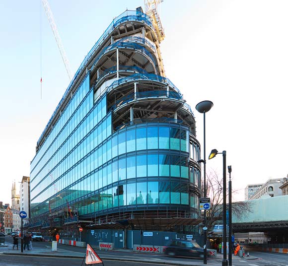
Creating a landmark

The project fits into a confined city centre site
Using a steel frame solution has helped form the flexible long-span floorplates required for a Manchester city centre commercial development.
FACT FILE
Landmark in St Peter’s Square, Manchester
Main client: Barings
Development manager: Castlebrook Investments
Architect: Squire & Partners
Main contractor: Bowmer + Kirkland
Structural engineer: Curtins
Steelwork contractor: Billington Structures
Steel tonnage: 1,800tStrong levels of demand are being experienced in the Manchester office market at present and, in order to satisfy this requirement, a number of new build commercial schemes are currently starting in the city centre.
One of only two wholly new developments due to complete in the city centre in 2019, the Landmark in St Peter’s Square is a 14-storey steel-framed building that will offer 16,700m² of BREEAM ‘Excellent’ office space and 50 car parking spaces in two levels of basement.
The steel frame offers clear spans and maximum flexibility for the floorplates, with an offset core situated along one elevation.
“The office floors have typically been designed to be column-free and only one column exists within the floorplate. Typically, secondary beams at 3m centres span approximately 17.6m from perimeter columns to the core, except at the south west and north east ends of the building where the secondary beams span onto a primary beam in lieu of the core,” says Curtins Structural Engineer Carl Bebbington.
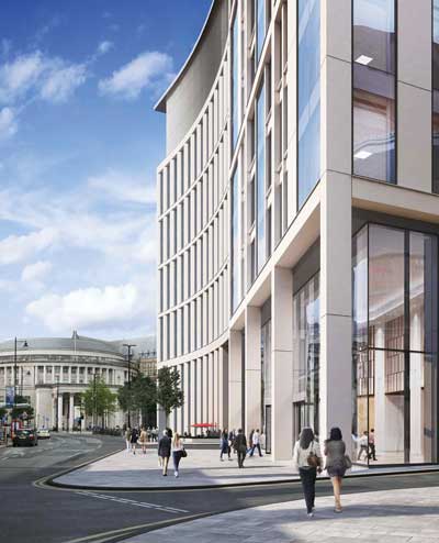
Visualisation of the completed scheme
Model showing the rear elevation and core
The main entrance foyer
A typical floorplate
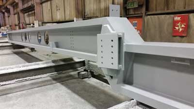
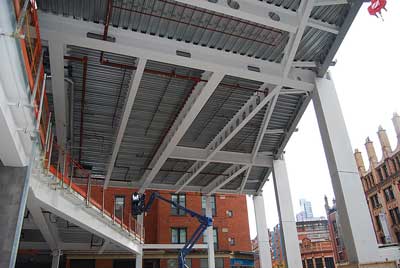
Fabricated plate girder for the building’s roof
Stephen Barrett, Squire & Partners Project Architect adds:
“From a spatial point of view a steel frame was chosen at the initial stages as this would allow for these larger spans, which provide an open-plan office space without any interruption.
“The benefits of steel also allow for a quicker programme in terms of installation and coordination of services, where steel beams can be penetrated offsite to allow sufficient openings for the distribution of services within the ceiling void.”
The structure’s one internal column is located close to the southern face of the core. Here the span from the core to the rear elevation is nearly 19m so, in order to keep the beam depth consistent with the rest of the building, a column was added.
If the design team had opted for a clear span in this area the beam required would have been very big, up to 1,200mm deep, and so the additional column was considered to be the most cost-effective solution.
The overall structure has a number of constraints which drove some interesting technical details, and one of these is the connection between the single internal column and the reinforced concrete basement support column beneath, through which around 20MN of force needed to be transferred.
Mr Bebbington explains: “To transfer the local bearing stresses between the two materials, an enlarged surface area was required, which exceeded the plan area of the concrete column below.
“This was achieved by casting a 2.85m steel section into the concrete, along with a number of shear studs which acted in combination with a stiffened baseplate to transfer the bearing stresses.”
For efficient service integration, plate girders with bespoke holes have been used throughout the structure to accommodate the services within their depth.
However, steelwork contractor Billington Structures says the beams have been over-engineered with more holes than are immediately needed, giving the building the flexibility to accommodate future tenants that may have more service needs than the anticipated immediate commercial user.
The structural frame also has a composite design, with the plate girder beams supporting metal decking and a concrete topping. This solution was chosen as it is the most economical way to create floors with long column-free spans.
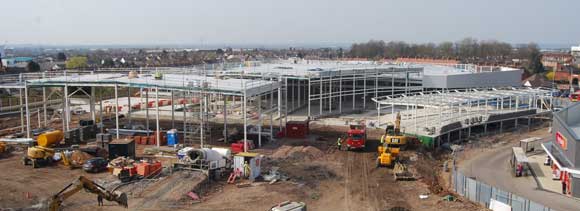
Steelwork forms the superstructure from the ground up but, before this part of the project began, main contractor Bowmer + Kirkland (B+K) had already completed some substantial preliminary substructure works.
Located on the plot of a former Odeon cinema, B+K started on site in early 2017 and commenced with a 21-week demolition programme. It then deepened the existing basement into a two-level subterranean zone, excavating the ground to its new 10m depth and surrounded the perimeter with a reinforced concrete liner wall.
Once these lower groundworks had been completed, which also included the installation of foundations and casting a ground floor slab, the steel erection was able to begin.
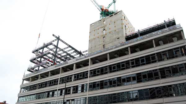
Steel erection followed on behind the slip-formed core construction, which was at level 10, when the first beams and columns were lifted into place.
“The building has one large core containing seven lift shafts and two staircases, which is a more efficient use of space as opposed to two separate cores,” says B+K Project Manager Mark Taylor.
As the core was constructed, Billington Structures supplied cast-in plates in readiness for its steel erection programme. Once its main work was under way, the company also installed steelwork and flooring inside the core to form access areas on each floor level.
The steel frame is fairly repetitive with every floor the same, with the exception of two set-backs located on the first and eleventh levels. The first floor is set back along the main Oxford Street elevation, creating a double-height entrance foyer.
Along this elevation, the perimeter columns have been encased with an architectural precast concrete finish in order to match the building’s overall cladding system.
A series of fabricated box sections, set back from the main columns, allows for a covered exterior pedestrian thoroughfare and supports the building’s two-storey high glazed reception elevation.
A number of transfer beams were required at level 11 to support the columns forming the upper set-back and terrace area.
“This led to a particularly heavy primary plate girder being used which was also supporting the floorplate’s long span beams,” says Mr Bebbington.
“As this member was at the far end of the structure, detailed tower crane planning was key to ensuring it was within the radius of reach and the crane’s capacities. The heavy end forces on this member created a challenge at the steel-to-concrete interface. Traditional studded cast-in plates were not feasible so instead a pocket detail was developed. This detail was developed in close collaboration with the site team and Billington to ensure buildability.”
The building’s main cladding system consists of precast panels, with each panel weighing up to 7t and measuring two storeys high. The panels are connected to a series of brackets, factory welded to all of the perimeter beams.
More than 2,700 brackets are needed to support the cladding and, because of the deflection criteria imposed on the steelwork, slightly larger members than would ordinarily be required were used for the building’s frame.
The Landmark is scheduled to complete in Summer 2019.