50 & 20 Years Ago
Design of two buildings with suspended structures
 The structures described in this article are two office tower blocks currently under construction (1967) for the Commercial Union Assurance Co. Ltd. and the P&O Steam Navigation Co., conceived as a comprehensive development on adjoining sites in the City of London.
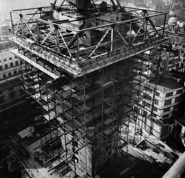
The CU Building is 387 ft high above ground level and 124 ft. square in plan. The entire tower is supported by a reinforced concrete core 75 ft. by 50 ft. in plan, and contains lifts, staircases and services. There are two plant rooms in the tower, one at mid-height and the other at the top. Each plant room contains steel frames cantilevering from the core to support trusses and girders around the perimeter of the building. The cantilevers reach 37 ft. out from the core on two sides of the building and 25 ft. out on the other two sides. Steel hangers within the external walls are suspended from the trusses and girders around the plant rooms and they support the outer ends of the castellated steel beams at each floor level. The inner ends of these beams are carried by the concrete core. Twelve office floors are supported by the hangers in the upper potion of the tower, and eleven office floors, an open podium and a mezzanine are suspended on the hangers in the lower half of the building.
The construction of the P&O Building is similar to that of the CU Building, but it is smaller in size, having one plant room at the top of the tower and ten office floors suspended from the cantilever steel work accommodated within this plant room. The height of this building is 191 ft.
Both buildings are enclosed in curtain walling with extruded aluminium mullions on a module of 6.31 ft. and the hangers are housed inside alternate mullions. The typical floors are of structural lightweight concrete generally 5 in. thick and span continuously over the castellated floor beams. The heating and ventilation services pass through holes in the castellated beams. At each floor level there is a composite concrete and steel truss around the buildings connecting all the hangers. This, with some overstress, will transfer the load from a failed hanger safely to the adjacent hangers.
The positions of the cantilever frames in the plant rooms are determined by the arrangement of the major walls in the core and, for the CU building, on two opposite sides of the tower there are two cantilever frames, whilst on the other two sides there are four. On the sides with two frames a deep truss, occupying the height of the plant room is used to transfer the hanger loads to the cantilever frames, while on the sides with four frames, a plate girder suffices.
The cantilever frames themselves comprise horizontal struts embedded in the plant room floor and diagonal ties connected to steel anchor blocks resting upon corbels formed in the concrete walls of the core. The horizontal component of the tension in the diagonal ties is transferred to the core by post tensioned prestressing cables that attach the anchor blocks to the core.
The horizontal struts in the cantilever frames are lattice box members connected to the perimeter trusses and girders through steel-to-steel end bearing plates. At the inner end the struts have steel bearing plates that thrust against the core walls. These struts also act as beams supporting the plant-room floors, and the vertical reactions due to this loading are resisted by steel brackets built into the core.
The steel lattice struts acting alone are only designed to resist the forces induced during the erection of the steelwork and the casting of the concrete plant room floor slab. The horizontal forces from subsequent dead and live loading applied to the structure are shared between the lattice strut and the 28 in thick lightweight concrete slab forming the plant room floor.
The curtain-walls for both buildings are supported by specially designed frames of extruded aluminium. The infilling panels of the CU Building will be entirely of grey tinted glass, extended from floor to ceiling of each room, with aluminium transom panels covering the depth of the floors and ceiling spaces.
 The Structural Steelwork.
There are approximately 2,500 tons of structural steel in the CU Tower, and 900 tons in the P&O Tower, of which a considerable proportion is high yield stress steel to BS 968:1962. The steelwork was generally designed to BS 449 using the elastic method.
The plate girders and the bottom chords of the trusses around the plant rooms are 4 ft deep and comprise high yield stress plates up to 2½ in. thick, welded together. All the other members in the trusses are of mild steel, plates being used for the diagonals and universal column sections for the top chords and the vertical posts.
The diagonal ties in the cantilever frames and also the blocks that anchor them to the core are fabricated from high yield stress plates up to 2¼ in. thick.
The hangers, too, are of high yield stress steel, their section ranging from 9 in. by 2 in. to 9 in. by ¾ in. The individual parts of the hangers are up to 66 ft long, spliced together with friction grip bolts.
The maximum working stress in the hangers is 13.5 ton/sq in. and there would be no advantage in using steel with a higher working stress because the extension of the hangers under the superimposed load is at the acceptable limit. Indeed, considerable attention was paid to the deflections of the suspended floors due to the superposition of the extension of the hangers themselves, the deflections of plant-floor steelwork and also the vertical creep and drying shrinkage of the core. The drilling of the hangers for the floor beam connections was arranged so that the floors will be level under the permanent load and about half of the superimposed load. The total extension of the hangers under permanent and superimposed loading amounted to 1.5 in. At the top of the hangers the drilling was varied from hanger to hanger to compensate for the deflections of the perimeter trusses and girders. It was simpler to do this than to camber the trusses and girders themselves.
Architects for both buildings were Gollins, Melvin, Ward & Partners. Consulting civil and structural engineers were Scott Wilson Kirkpatrick & Partners.
Reprinted from Building with Steel Volume 4 No. 8
November 1967