Projects and Features
High speed rail college set to arrive
Double doors in the eastern end of the workshop will allow access for two railway lines
In anticipation of the construction of high-speed rail infrastructure, a national college to train specialist engineers is being built. Martin Cooper reports from Doncaster.
FACT FILE
National College for High Speed Rail, Doncaster
Main client: Doncaster Metropolitan Borough Council
Architect: Bond Bryan Architects
Main contractor: Willmott Dixon
Structural engineer: Curtins
Steelwork contractor: Hambleton Steel
Steel tonnage: 760tAs one of the UK’s historic railway manufacturing centres it is fitting that Doncaster is one of two sites chosen to house the National College for High Speed Rail (NCHSR).
With another sister college building under construction in Birmingham the NCHSR is described as one college on two sites.
It will train the thousands of new engineers needed to deliver billions of pounds worth of rail contracts over the coming decades, including the new HS2 high speed rail line.
Transport Minister Robert Goodwill said: “We’re going to need 25,000 people to build this railway. We’re going to need a lot of technical skills and this college is all about equipping our people with the skills they’ll need, so we don’t have to bring them in from elsewhere.”
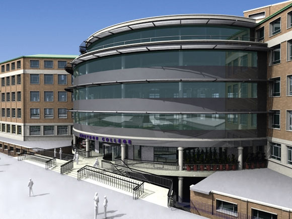
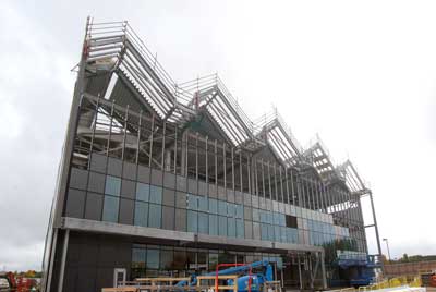
The ultra-modern steel-framed facility at Doncaster is located within walking distance of household names in the rail industry like DB Schenker, Volker Rail and Hitachi. The location is said to offer easy access for employers and students from across the UK.
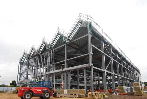
Doncaster’s industrial heritage is represented in the building’s roof design

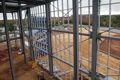
The workshop’s rail tracks are overlooked by classrooms
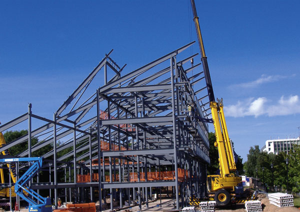
The eastern elevation during construction
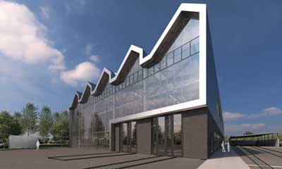
The eastern elevation after completion
The Doncaster college will comprise 7,600m² of teaching and workshop space and includes significant specialist rail equipment such as 150m of external track and catenary.
The college building is topped with a saw-toothed roof, which is a nod to Doncaster’s industrial heritage and also a way to install sustainability. The southern slopes of the saw-tooth ridges will have solar panels, enough to supply a high percentage of the college’s electricity needs, while the northern ridges will have roof lights allowing natural light to flood into the interior of the building.
According to project structural engineer Curtins, this innovative roof design required careful design and detailing to get the structure to perform within the deflection criteria for the building.
Main contractor for the project is Willmott Dixon and it started work on the previously greenfield site in January 2016. Early works included the installation of piles in preparation of the steel frame being erected.
Hambleton Steel fabricated, supplied and erected the project’s structural steelwork along with installing metal decking, precast flooring planks and precast stairs.
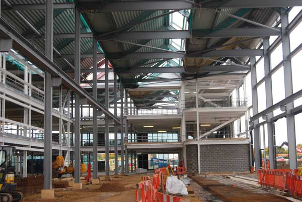
Within the 120m-long structure there is a 1,900m² workshop area containing dual railway tracks accessed via a double door in the eastern elevation.
The workshop is a double-span area with one 16m clear span accommodating two railway tracks and a second 8m-wide span housing rail maintenance areas.
“The long spans required for the workshop, as well as other areas within the college, was the main reason why steel was chosen for the project,” says Willmott Dixon Construction Manager Roger Morton.
Columns for the workshop and the entire building are predominantly based around a grid pattern of 8m centres. Columns are mostly 305 × 305 × 118 UC sections, however along the workshop’s outside elevation larger 610 UB sections have been used.
“These larger members add stiffness to the structural frame,” says Richard Osbond, Curtins Technical Director. “The structure is a braced box and this works really well for the teaching areas, but as the workshop area is 14m-high the columns needed to be stiffer for overall stability.”
Crane loadings also had to be taken into account as the columns within the workshop also support crane rails that will allow a gantry crane to operate within the building.
Bracing for the workshop is located at the gable end and in some bays.
Forming an L-shape, three-floors of teaching spaces wrap around two sides of the workshop. In this part of the structure the bracing is mostly located in partition walls and around the lift and stair cores.
The teaching spaces will include classrooms, informal learning areas, open project spaces, a 120 seat capacity lecture area, seminar and meeting rooms and an atrium social area open to the public.
Within the atrium there will be a coffee area on the ground floor and a catering kitchen on the second floor with seating for about 200 people enjoying views out of the building and across the workshop.
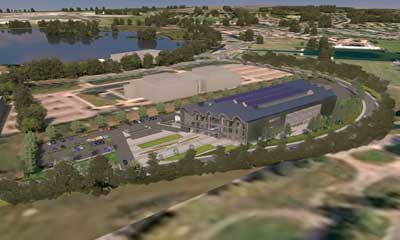
Impression of the finished site
A combination of metal decking and precast planks have been used for the building’s floors. The metal decking solution was deemed a better option for the longer spans, such as over the atrium and other circulation areas. Within the teaching spaces, Willmott Dixon chose to use precast planks as they were considered to be a better way to aid service integration within the floors.
Willmott Dixon was chosen by Doncaster Metropolitan Borough Council through Scape Group’s National Major Works framework to the NCHSR.
Summing up, Mark Robinson, Scape Group Chief Executive says: “HS2 is essential to rebalancing our economy and creating a Northern Powerhouse. A project of this scale requires a fresh pool of talent equipped with a wide range of skillsets. Over 2,000 apprenticeships will be created by HS2 with 25,000 employed during its construction, which will be a substantial boost to our industry talent pool. We’re excited to be playing a crucial role in a project to rekindle a sense of pride in careers in construction as well as helping to create a consistently strong UK PLC.”
The NCHSR is scheduled to open its doors for the first intake of students in September 2017.
 The design of crane girders
The key design criteria for crane girders is often deflection, in both directions. In addition to vertical deflection, lateral forces from the crane operation cause lateral deflections. A traditional approach to the design of crane girders was to weld a second component to the top flange – either a plate or a channel (toes pointing down, over the flange).This additional member was designed to resist the lateral bending, and the crane girder designed for the vertical forces. A further design requirement with crane girders is to control the spread between the two rails, which is often a challenge when crane girders are connected to portal frames – the portal columns spread under vertical load. In the NCHSR, columns supporting the crane girders span from floor to roof and are braced at roof level, so the spread between crane rails is controlled by the bending resistance of the columns.
Crane girders demand onerous tolerances, so provision of adjustment is important. In the NCHSR crane girders are supported on brackets welded to the column flange. Opportunity for adjustment vertically and laterally is provided at the connection between the bracket and the crane girder by allowing for packs.
Within the Eurocode suite of Standards, guidance is provided both for the crane loading and the structural resistance. BS EN 1991-3 covers actions induced by cranes. This Standard covers lateral, longitudinal and vertical loads and is not simple. Some crane manufacturers provide data in a format directly compatible with BS EN 1991-3, which is a significant advantage for the structural designer. The resistance of crane girders is covered in BS EN 1993-6. Crane girders are obviously unrestrained between supports, with the vertical load applied to the crane rail, above the top flange. Although this would normally be a destabilising load, if the crane rail is fixed directly to the crane girder (as is the case at the NCHSR), the wheel loads actually apply a restoring moment if the girder starts to twist. The Standard allows this benefit to be included in design. The Standard is also notable for an expression covering the interaction of lateral torsional buckling, minor axis buckling and the torsional moment.
A comprehensive example of crane loading can be found by an internet search for “design example actions induced by cranes and machinery sedlacek”. A numerical example of crane girder resistance can be found in Example 2 of P385 – Design of steel beams in torsion. Guidance on the fatigue design of crane beams is anticipated to be published by BCSA in 2017.
David Brown – SCI