Projects and Features
Courtroom appeal
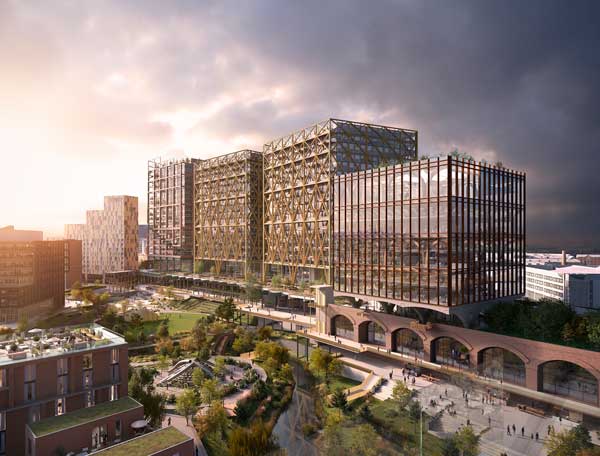
Manchester’s new Civil Justice Centre dramatically rethinks what a court building should look like.
FACT FILE: Manchester Civil Justice Centre
Developer: Allied London Properties
Design & build contractor: Bovis Lend Lease
Architect: Denton Corker Marshall
Structural and services engineer: Connell Mott MacDonald
Steelwork contractor: William Hare Ltd
Steelwork tonnage: 3,000t
Contract value: £165m
Think of a court building and the image that comes to mind is most likely a forbidding, staid, perhaps intimidating mass.
The new Civil Justice Centre currently under construction in Manchester is a decisive break with tradition. One elevation is given over to a light, airy atrium in which triangular columns soar to the full 11-storey height; the main block, which contains 47 courtrooms, features dramatic cantilevering ‘fingers’ up to four storeys high projecting from each end.
The design was chosen in an international competition, won by a team comprising Connell Mott MacDonald, the multidisciplinary building design alliance of the UK’s Mott MacDonald and Australia’s Connell Wagner, with architect Denton Corker Marshall.

Courtrooms will be housed in cantilevered fingers, glazed at the end
")
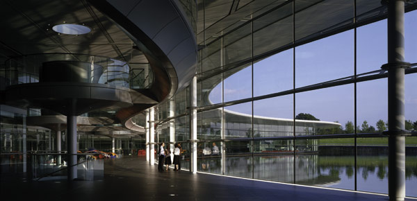
Triangular hollow section columns in the atrium rise 60m

The cantilevers were assembled at the works, cut into sections for delivery to site and bolted together, before lifting into place (below)
")
The cantilevers were pre-assembled before lifting into place

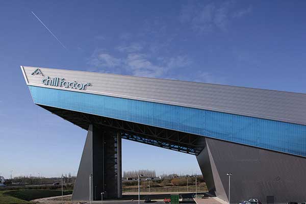
The environmental veil adds shading
")
Pods in the atrium provide meeting rooms

William Hare was the steelwork contractor on the Manchester Civil Justice Centre
DCM Associate Wojciech Pluta says: “We were trying to break down the old model of court buildings being imposing and monolithic.”
He adds that one reason he believes the consortium won the competition was a decision to move the main entrance, which the client originally asked to be on the minor Hardman Street elevation, to Bridge Street, one of Manchester’s main thoroughfares. “One of the main functions of the building is that it will be a marker on the way into the city, approaching along Bridge Street, a historic main route. Having the main entrance on Bridge Street gives it a link to the Town Hall and Art Gallery.”
The building is conceived as different ‘layers’ with different functions and degrees of transparency. The atrium contains the public areas, including a 3.2m wide concourse at each level which provides for horizontal circulation around the building, and is designed to allow members of the public to orientate themselves. ‘Pods’ within the atrium will provide self-contained meeting rooms for solicitors and their clients, and are designed to appear as if suspended in mid-air.
A solid spine forms the next layer and contains lifts and stairs as well as more meeting rooms. It acts as a link to the next layer, containing the courtrooms, judges’ chambers, administrative offices and a library.
The cantilevering fingers are fully glazed, though since they contain courtrooms this will have limited transparency. However Mr Pluta stresses that there will be views from the end of each courtroom and the sky will be visible through high level glazing along each side.
The final layer, 600mm outside the line of the Bridge Street façade, is the metal ‘environmental veil’, whose different panels have varying degrees of perforation to suit the rooms behind, providing shading or reflecting natural light into the building as required.
The building has an irregular grid, and floor to ceiling heights of 5.6m up to level 11, the court areas. The administrative offices are mainly on the four floors above and have more usual ceiling heights.
Maximum floor span for the courtroom areas is 11.5m, and the vibration response of these long span areas was looked into in detail. “We did a lot of modelling of floor vibration,” says CMM Principal Engineer Mark Thompson. CMM bridge engineers wrote specialist software to model the resonances, peak amplitudes and so on generated by a person walking around the floor.
“We developed the design requirements with DCM and with an acoustics company assisting in establishing what the design criteria should be,” says Mr Thompson. A response factor twice as stringent as the normal standard for offices was adopted. To achieve this, a vibration damping beam has been added in the 11.5m span areas, consisting of a 600mm square mass concrete ‘beam’ contained in permanent shuttering fabricated from folded steel sheet.
Perhaps the most complex aspect of the building structurally was the cantilevering fingers.
“These are designed as trusses,” says Mr Thompson. High tensile forces are produced at the top of each finger and high compression at the bottom. These forces are distributed through the composite steel deck floors, via tension reinforcement where appropriate, to the main slipformed concrete core.
The component members of each finger are made from plated sections generally 450mm deep and 220mm wide. Typically the flanges are in 30mm plate with 15mm webs.
Two headaches were the construction sequence and the issue of progressive collapse. “The initial design required all the concrete floor plates of the main block to be cast and to have reached their 28-day strength before erecting the fingers. To save time we developed a temporary works solution with William Hare to allow faster erection.” This allowed for every third floor to be cast, with the introduction of temporary diagonal props from each finger down to the concreted level.
To meet the requirements for progressive collapse, the structure has to be capable of continuing to stand up after the removal of one element. Key elements of the structure can be designed to withstand the notional force of an explosion, or alternative load paths have to be found.
“We looked at designing the truss members as key elements,” says Mr Thompson, “but it wasn’t practical. Instead, we designed it so that if you lose any member it would support the load through moment frame action. There would be increased distortion but it would remain stable.”
The complete trusses, up to four storeys high, were fabricated and welded together at William Hare’s works with the correct built-in precamber. The whole unit is too heavy to lift as one, so each truss was then cut through the diagonals into sections to be bolted together again on site.
Because of their size, each unit needed a police escort and had to be delivered to site after 7pm. Because the site is extremely cramped it had been expected that it would be necessary to close Bridge Street while the fingers were lifted into place. “In the end, up to level nine we put up with a mobile crane either side from within the site boundary. For the rest the site tower cranes were used,” says Mr Moylan.
The pods were also assembled on site and lifted into place as a unit.
Rising the full height of the atrium is a row of 700mm hollow equilateral triangular columns. These are restrained at irregular intervals by the beams which also support the pods. Generally they are designed to run for three storeys between restraints — nearly 18m because of the height of the courtrooms. Differential thermal movement between the columns and the façade of the atrium had to be provided for, using sliding movement joints between the façade support structure and the main structure.
The columns are made from steel plate 15mm, 20mm or 35mm thick depending on the load on the column, welded together at each vertex of the triangle. Achieving the sharp edge detail the architect wanted at each corner of the columns was a challenge for steelwork fabricator William Hare. A number of solutions were mocked up and eventually a detail in which the welded joint is squared off to 15mm wide, rather than attempting to achieve a perfect point, was adopted.
With 2500m of welding in total, getting a consistent finish was a worry, admits William Hare Project Manager Dave Moylan. “We were concerned about getting consistency, but in he end there wasn’t the degree of difficulty we expected. The consistency was very impressive.” He adds: “In the first week we did one column; the second week we did two, the third we did three, and after that we managed four a week.”
There are two splices in the 60m high columns; a temporary bolted joint is used during erection, and the joint is site-welded later. For fire resistance the columns are filled with concrete to the height of the bottom storey.
William Hare’s designers worked closely with the rest of the design team from an early stage, constructing a model in Strucad. This included details such as the frame for the glazing system and allowed areas of conflict and missing information to be identified and resolved prior to fabrication.
Bovis Lend Lease project manager Peter Foy says the project has run extremely smoothly because of early involvement with CMM and William Hare. “We had 12 months’ discussion with CMM and the steelwork contractor, and we spoke to the market place about buildability and methodology. We spent time setting up the site and building a service road as the focal point for the logistics operations.” The service road is a substantial construction, built on piles after the demolition of a former car park, which took place during a 26 weeks of enabling works at the start of the 156-week contract.
There were also early discussions and presentations to the Health and Safety Executive on proposed working methods as part of Bovis Lend Lease’s Incident and Injury Free campaign.
Following a topping out ceremony in July, the main structure was on track for completion last month, on the way to an opening date in spring 2007.
Part of the service
")
The complex service layouts of the pods were modelled with the structure in 3D
Connell Mott MacDonald’s multidisciplinary approach to structure and services paid dividends, says Principal Engineer Mark Thompson.
The client called for the building to be naturally ventilated as far as possible, which meant the structure had to be designed to accommodate a complex web of ductwork to allow air taken in at the sides of the atrium, through vents facing the direction of the prevailing wind, to circulate through the entire building.
“We did a lot of modelling of how the wind and air was distributed through the building,” says Mr Thompson. The natural ventilation system is designed to maximise free cooling potential and comfort in mide-season. An intelligent building management system brings in a backup forced ventilation system if the wind speed is too slow to achieve this.
“Co-ordinating the structure and services as well as meeting the architects’ requirements was a big challenge,” says Mr Thompson. In locations such as the pods, a 3D model of the structure and services was created. “We even had to co-ordinate the secondary purlins with the services,” says Mr Thompson. “If there had been separate M&E and structures firms it would have been substantially more challenging.”