Projects and Features
Steel provides architect’s vision

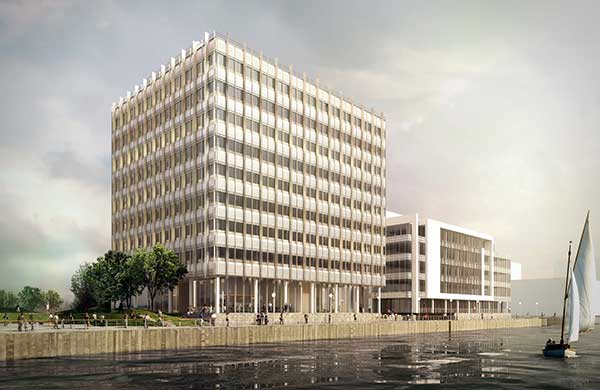
One Tudor Street is situated on a confined site formerly occupied by Unilever House’s annexe
Cost, efficiency as well as a number of challenges associated with existing foundations were all overcome with the use of a steel frame on a new commercial block in the City of London.
FACT FILE: One Tudor Street, London
Main client: Stockland
Architect: TP Bennett
Main contractor: Balfour Beatty Construction
Structural engineer: Upton McGougan
Steelwork contractor: Bourne Steel
Steel tonnage: 845t
Project value: £20M
New commercial buildings are continuing to top out in the City of London despite the current doom and gloom associated with the credit crunch. An example is One Tudor Street, a new six-storey office building, with two basement levels, situated on the site of the former north wing of Unilever House which will offer 6,555m² of grade A office space.
The structure is steel framed and based around a large 10.5m x 9.5m grid pattern, which gives the building the required open plan environment. Stability is predominantly derived from one braced core and an eight level high moment frame located one grid line back from the structure’s Tudor Street elevation.
Many high-rise commercial developments are steel framed for reasons of cost, efficiency and speed of construction. One Tudor Street is no exception as Patrick Fisher, Associate at Upton McGougan explains: “During the initial design stages we looked at a number of framing solutions and a steel frame quickly emerged as the most economic solution for this particular grid arrangement.”
Once the design process was under way height became an issue as the site falls within sight lines of St Paul’s Cathedral and consequently there was a limit imposed on the number of allowed floors. To maximise the number of floors cellular beams – approximately 290t in total – have been used to allow the services to run within the structural zone.
Interestingly, the cellular beams have been slightly modified with a crank detail attached to the end of the member, and so reducing the section size from a 533 beam to a 305. This was done to form a thin structural junction, at each floor level, along the external elevations.

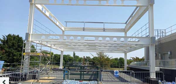
A vierendeel truss was erected to cantilever over subterranean obstructions
A vierendeel truss was erected to cantilever over subterranean obstructions

Long 10.5m spans are a feature of all floors

The steel frame model
“It was a feature developed with the architect,” explains Mr Fisher. “It forms a visually thin floor zone when viewed from outside and also creates a raised ceiling zone adjacent to the external façade.”
The crank detail consists of a smaller end section positioned level with the top of the concrete floor and butt welded to the main cellular floor beams.
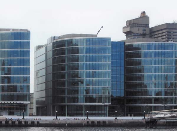
Also for architectural and aesthetic value, the building’s two street-facing façades are adorned with a single row of 12.2m high feature columns which begin at upper basement level and top out at first floor level.
Another major consideration during the design stage was below ground where existing piles had to be retained. Consequently new piled foundations had to be arranged around these piles and this led to the requirement for reduced foundation loads, which again favoured the use of steel.
Early works in the construction programme also included the demolition of the existing building which had a two level deep basement. New pile caps and ground beams were installed around these existing piles, adding to the complexity of the early works.
“Given the current drive in the industry for foundation reuse we undertook an extensive review into the possibility, the existing foundations are 20m long under-reamed piles, however more for commercial/insurance rather than technical reasons the reuse option was eventually discounted,” adds Mr Fisher.
As the new steel frame starts at basement level and the design required the grid pattern to remain constant throughout the structure, a number of columns are positioned directly above existing piles. Bigger-than-normal ground beams, transferring the loads to the new pile caps had to be installed.
In one location, adjacent to the southern elevation, three piles could not be installed because of a series of major obstructions. These piles provided support to a major perimeter column and with the inability to provide support directly beneath it, an alternative structural solution needed to be found. The solution was a storey high braced vierendeel girder which was capable of cantilevering back to an area where new piles could be installed.
Along an adjacent party wall, in the north west corner of the site, an existing concrete stairwell core was also retained as it was structurally integral to the next building. This feature has been incorporated into the new building with the new steelwork coming off of it.
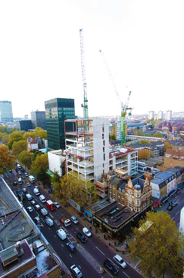
All steelwork was erected by Bourne Steel during a 16 week programme, which also included the installation of metal decking and stairs. Steel was erected two floors at a time with column splices at every 7m.
“The erection process went to plan and towards the end of February this year we just had to come back and infill the hole where the tower crane had been,” explains Nick Hatton, Bourne Steel Divisional Operations Director.
Although as previously mentioned stability is mostly derived from a major braced core located in the south west corner of the site, the structural design also had to incorporate a large moment frame which was erected along with the main steelwork.
As the majority of the building is open plan with a limited number of internal columns, locations for bracing were extremely limited due to the glazed facades of the structure. Vertical bracing was used in the north west core, but with its small plan area the aspect ratio proved too great to keep building deflections within limits.
The solution was the introduction of an eight-storey moment frame to act in conjunction with the north west core’s vertical bracing. “This reduced horizontal deflections to acceptable levels without losing floor space,” adds Mr Fisher.
Completion of the project is scheduled for July 2009.