SSDA Awards
SSDA Award: More London Plot 1
 Architect Foster and Partners
Structural Engineer Arup
Steelwork Contractor Severfield-Reeve Structures Ltd
Main Contractor McAlpine-Mace JV
Client More London Development Ltd
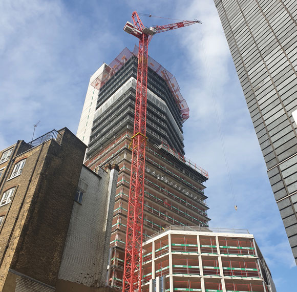
More London Plot 1 is an £85M office development on the south bank of the River Thames in London adjacent to HMS Belfast, to the west of Tower Bridge. It consists of three 10-storey buildings with car parking, loading bays and some lettable space in a basement covering the entire site. Plantrooms are located on the roof, set back from the building perimeter and enclosed by a louvred screen. Two of the buildings, Plot 1A, are linked by a full height atrium with bridge links at every level. The third building, Plot 1B, is completely separate.
The superstructure consists of concrete/steel metal decking floors supported by a steel frame consisting of Fabsec beams spanning up to 22.5m and UC columns. Lateral stability for each building of Plot 1A is provided by a concrete box core located about mid-way along the length. Lateral stability of Plot 1B is provided by two concrete cores. The atrium structure consists of a glazed wall facing the river views and a glazed roof supported by a steel hollow section structure.
 The scheme for Plot 1A was originally based on an 11.5m grid across the building with a central column on grid. During development of the scheme design the client asked what the consequences would be of eliminating the columns within the office floor plate, thus creating a 22.5m span, whilst maintaining the same overall floor depth. The benefits were added flexibility in the planning of the internal space, which would give the building an edge in the office letting market. The additional cost due to the increase in steel weight was evaluated and accepted by the client and the building was pre-let. This was crucial to the viability of the project in an oversupplied market.
Although the revised design met the brief upper limits for pedestrian induced floor vibrations (Response Factor (RF) = 8) the client was advised that there was recent evidence of increased office worker sensitivity to floor vibrations. The introduction of flat computer screens mounted on arms projecting from office furniture had resulted in complaints from users who were experiencing difficulties reading text displayed on their screens. The problem was attributed to floor vibrations. In cases investigated by Arup the level of floor vibration was around RF=8, which is the generally accepted upper limit for normal offices.
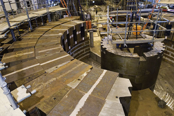
 It was decided to investigate the possibility of a cost-effective method of significantly reducing floor vibrations by providing additional damping. The idea of using a bituminous damping layer sandwiched between steel and concrete had been developed and used successfully on the long span spiral ramp structure in the atrium of the neighbouring City Hall building completed in 2002. In the case of City Hall the concrete was a non-structural topping covering the entire ramp and the damping layer similarly occupied the entire width. For More London Plot 1A the width of the damping layer is restricted to the width of the steel beams. A thin layer of bituminous material is sandwiched between two metal plates and placed between the top flange of the steel beam and the metal decking towards the ends of the beam. Composite action is maintained by providing shear studs over the central portion where the damping layer is absent. To test the effectiveness of the system, computer models of the concrete slab, shear studs, steel beam and damping layer, characterised by a ‘loss factor’, were analysed using the advanced finite element package NASTRAN and subject to transient dynamic loading. The results obtained were compared to similar analyses where the damping layer was omitted. The results showed that significant improvements in damping were feasible. Using this system a 22.5m span floor can achieve RF=6 or less without the need to increase depth or mass beyond that required for strength design. The idea was presented to the client and received favourably.
The solution adopted for the long spans is a 720mm deep Fabsec beam with 400mm diameter web holes, supporting a 130mm deep concrete floor slab. The 850 deep structure occupies the entire depth between the raised floor and false ceiling with the airconditioning ductwork passing through the web holes.
Floor vibrations were assessed by calculating the vibration modes of the floor structure using a computer model consisting of steel beams offset vertically from a finite element model of the concrete floor. Response was then assessed by calculating the walking pace that would cause resonance for a particular vibration mode and then combining the response of all the vibration modes that could be excited by a person walking at this pace. Typically the lower frequency modes, around 3Hz, are excited by the first harmonic of the walking input, whilst the higher harmonics excite higher frequency modes.
 Time was short since construction of the foundations and basement had commenced. A potential manufacturer of the product, Richard Lees Steel Decking (RLSD), was approached and registered enthusiastic interest. Two test panels, each consisting of two 12m long simply supported steel edge beams supporting a 3m width of concrete slab on metal decking were constructed by RLSD; one with the damping layer and one without. Vibration testing, carried out by Arup, consisted of attaching an accelerometer to the middle of the beams and measuring the natural frequency and damping due to a heel-drop at midspan, and the acceleration response due to a person walking along the middle of the slab, from end to end, parallel to the beams, at a walking pace chosen to excite the lowest natural frequency of the beams. The walker carried a hand-held metronome set to the desired pace. The results confirmed the analytical findings.
Following the testing and analysis of the results the decision was made to incorporate the damping system into the Plot 1A buildings. Safe erection methods for the decking in the absence of studs and the damping layer sandwich were developed with the decking supplier and main contractor and incorporated into the erection method statement.
Post-construction, further testing was carried out by attaching an accelerometer to the middle of the critical areas of the floor and measuring the real natural frequency and damping due to a heel-drop at the same location.
The building is now fully occupied and favourable comments on the feel of the floors have been received. The cost of significantly reducing floor vibrations was approximately £2/m² of floor area. The damping layer is now an RLSD product called “Resotec”.
Judges Comment
As can be expected with this team, the development pushes the design process to the limit in meeting the client’s brief for large open office space that is essentially column-free and environmentally efficient and controlled, whilst taking full advantage of the superb views of its riverside location. It has achieved a simple, clear design that is logical in its master-planning, sophisticated in its detailing and uncompromising in its execution. The result is a classic of its type.