Projects and Features
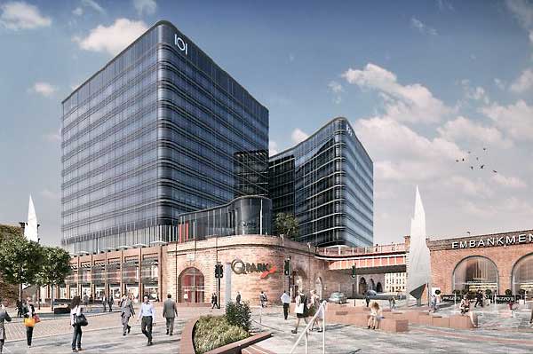
Signature structure highlights regeneration
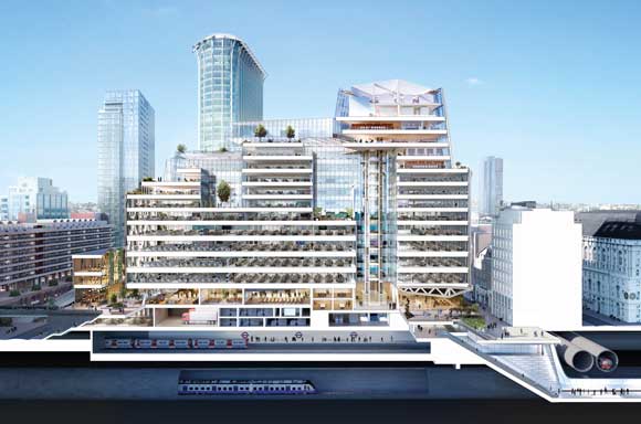
Visualisation showing the numerous underground constraints
Spanning an important London underground station and featuring an architecturally-detailed exposed steel frame, 21 Moorfields is a feat of engineering. Martin Cooper reports.
FACT FILE
21 Moorfields, London
Main client: Landsec
Architect: WilkinsonEyre
Main contractor: Sir Robert McAlpine
Structural engineer: Robert Bird Group
Steelwork contractor: William Hare
Steel tonnage: 17,000tConstruction of the eagerly anticipated Crossrail (Elizabeth Line) scheme has been the catalyst for the regeneration of the previously undervalued Moorgate area of the City of London.
A number of new and recently completed commercial buildings have helped to breathe new life into the area, while the western ticket hall to Liverpool Street Elizabeth Line station, which is adjacent to Moorgate underground station, will ensure an increased footfall, once the rail scheme opens in 2021.
Located directly above Moorgate’s underground and Crossrail assets, another commercial development known as 21 Moorfields is predicted to further regenerate the area, while also enhancing the urban landscape of this transportation hub with its eye-catching exposed steelwork design.
Pre-let to Deutsche Bank as its new London headquarters, the 17-storey building is also a complex engineering feat, with a steel frame that spans the full width of the station, a distance which is equivalent in length to the wingspan of a jumbo jet.
Prior to construction beginning, a number of design proposals had been put forward for the site, which had been vacant for a number of years. But as Robert Bird Group (RBG) Associate Director Chris Papanastasiou explains, the current design was the most viable.
Model showing the trusses and mega-arches
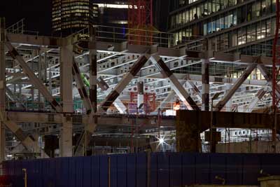
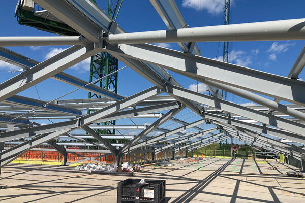
Trusses span over the station assets
The Moorgate façade will feature a seven-storey exposed truss
Maximising the usable capacity of the existing slab, which is also the station roof, the structural design features six 7m-deep ‘Launching Trusses’, up to 55m in length, built up from, and subsequently spanning over, the station below to create temporary support for the floors above during the construction programme. In the building’s completed form, the trusses revert to permanent features within the circulation spaces.
The building’s first floor and main entrance level as well as a mezzanine (second floor) are accommodated within the truss depth. Below the trusses, the existing slab supports a basement, at ground floor level, for the building’s back-of-house and plant equipment areas.
During construction, each truss facilitates the construction of a 10-storey steel fabricated box section mega arch, which in turn, once completed, enables the construction of the concrete floor slabs and the remaining steel frame.
The mega arches are integrated into the building’s cores up to level 7, only exiting on to the floorplates at levels 7 to 10, thereby minimising the number of columns present within each 100m long, 60m wide floorplate to only six.
Above the mega arches, the structure continues upwards in a more traditional beam and column design to level 17, with stability provided by braced steel cores, minimising dead weight on the foundations. Incorporated into these floors are terraces and set-backs to satisfy a number of rights to light issues, and historical sight paths to St Paul’s cathedral.
“The combined solution of low-level temporary / permanent launching trusses, mega arches, and a construction methodology developed largely by RBG, offered an efficient solution to this heavily constrained site. One that allowed the building to work in terms of cost and floor area, whilst allowing the station to remain open throughout the construction programme, thereby providing the design’s important viability,” explains Mr Papanastasiou.
Before any steelwork could be erected on site, a piling conundrum had to be solved. There are a number of constraints below the site, including six London Underground lines, two Crossrail tunnels and a ticket hall, station services and a major sewer. All of which meant that locations for any new piles were extremely limited.
A total of 16 piles, each 2.4m or 1.8m in diameter and 60m-long, were threaded between the numerous under-site constraints. Each pile is working extremely hard, and according to RBG they are all working to their upmost capacity and there may not be any foundation solution in London that is working harder.
Finding the spaces for the piles was one challenge, but getting a piling rig onto site was another. The existing slab over the live Moorgate station did not have sufficient capacity to support a rig, so RBG, in conjunction with steelwork contractor William Hare, designed a 2,000t temporary steel grillage that covered most of the existing deck.
This temporary piling rig support was assembled onsite with numerous beams that supported 20mm-thick steel plate sections.
Once the piling had been completed, RBG and William Hare were able to reuse much of the grillage as temporary steelwork to support the launching truss installation, which contributed to reducing the carbon footprint of the building.
Each truss/arch system is connected to, and founded on, a pile at each end but, because of the limited locations, the spacing between each truss and the shape of each arch varies. The piles and their locations have consequently dictated the column lines for the entire superstructure.
“The longest grid spacing is 21m and the beams that span this gap had to be brought to site in two pieces as they were too long to be transported through the City of London,” says William Hare Project Director Francisco Loureiro.
“All of the steelwork, including the trusses, has to be brought to site in sections that are within the tower crane’s lifting capacity. To maximise the crane usage and to reduce the amount of pieces requiring site connections, the trusses were delivered in pieces of up to 25t.”
Connected to the trusses is a series of large nodes that in turn connect to the arches and adjoining steelwork. With numerous connections, the nodes weigh up to 20t each and had to be brought to site on trestles.
“Because the site is very constrained with little room for manoeuvring the steelwork, each node was placed on a trestle in a position that allowed it to be lifted straight from the truck and into its final position,” explains Mr Loureiro.
As well as the arches, the trusses also support columns along their width that form the upper levels of the scheme. The columns are arranged in a primary grid of 12m with a secondary grid accommodating spans of 13.5m up to 21m.
Maximising the project’s footprint, the eastern façade (along Moorgate) cantilevers out over the Crossrail ticket office with a seven-storey, fully-exposed perimeter truss creating a signpost for the building’s main entrance below.
The cantilever is created by a combination of tripod supports from foundations inboard of the perimeter, and a series of bowstring trusses, measuring 25m-long and each weighing 70t. The bowstring trusses are hung from the east face truss over the Crossrail station, while the building footprint is further cantilevered at either end by a tripod structure at the south-east corner and a large V-frame at the north-east end.
The underside of the bowstring trusses (soffit) will be lit up in the completed scheme, drawing people into the building and towards the main central full-height atrium.
Similar to many other steel elements on the project, the bowstring trusses were designed with the site’s tower crane capacities in mind, and consequently they were detailed as compound sections and fabricated in six pieces, which were spliced together during the erection programme.
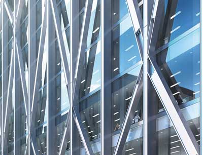
“The east truss, like much of the structure’s steelwork, has been designed to be lean and efficient, with force paths reflected in the size and weight of sections. All of the detailing is expressed, as the entire truss will be exposed and so the connections are all flush. The nodes are also detailed to highlight the bolts as they will be on show,” says WilkinsonEyre Associate Director Melissa Clinch.
The tripod is fabricated from box sections and, as the name suggests, it has three arms that radiate outwards from its 10m-high top. The base is founded on a concrete column, which is positioned within the Crossrail ticket hall and was designed and constructed as part of the rail project’s package in preparation for an over-site development, completing the array of challenging site constraints.
Melissa Clinch says the project team along with the client – Landsec – trialled an enhanced procurement process, focussed on collaboration to find the most suitable suppliers to ensure maximum efficiency on this complex development.
“William Hare were brought on board at an early stage and this helped us work out how each piece of steel could be fabricated, detailed and, importantly, delivered to site.”
Summing up, Sir Robert McAlpine Project Director Bob Kay says: “This project demonstrates what is possible if you really put your mind to it. The complexity of the structure with limited points of support could only be delivered with a steel frame.
“21 Moorfields could well prove to be a template for numerous over-site developments in London and shows that they can be used to create some fantastic architecture and valuable assets.”
21 Moorfields is due to be complete in early 2021.
Site welds
David Brown of the SCI comments on the site welds to be completed at 21 Moorfields
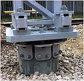
 One of the themes at 21 Moorfields is the sense of magnitude. Long spans, “mega” arches, with load focussed on a small number of piles – a theme which continues with the connections.
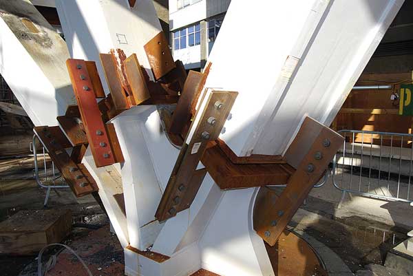
The connections shown (in picture right) are very large site welds between the members and the fabricated node. The plates on the faces are temporary, used to align the members and hold them in position whilst the welding is completed. Some appreciation of the very large welds can be seen by looking closely at the size of the preparation on the members – the welds are huge.
Welded details like this demand specialist expertise, which will be provided by the Responsible Welding Coordinator (RWC), a required role for CE Marked steelwork. Although these welds at 21 Moorfields are unusually large, the same principles apply to all welds. Welding procedures will be prepared, designed to avoid cracking in the weld and heat affected zone. The weld procedures reflect the Carbon Equivalent Value (CEV) of the parent material and the combined thickness at the weld, which is the total thickness of material in each direction at the joint. More material means a larger heat sink, allowing faster cooling, which increases the risk of cracking. Similarly, a higher CEV increases the risk of cracking. The RWC will specify a welding consumable with a particular hydrogen scale (less hydrogen reduces the risk of cracking). The RWC will also specify the welding parameters – the electrical parameters, consumable size and travel speed, which affect the heat input – another variable to be carefully managed.
Designers will find the figures in BS EN 1011-2 educational and useful background, as the figures relate CEV, hydrogen scale, heat input and combined thickness to necessary preheat temperatures. Designers should treat this as educational only – the responsibility lies with the RWC, for all welds, not just the welds at 21 Moorfields.
The individual completing the welds will be appropriately qualified, and for certain, the welds will be tested on completion. All of these issues are addressed in Section 7 of BS EN 1090.
The site welds at 21 Moorfields are completely different in scale and significance to the common 6 mm or 8 mm fillet welds, but demonstrate that with careful thought, planning and expert input, even the large site welds shown can be completed successfully.
Further reading
Guide to site welding (SCI publication P161)
SIGNS SN08, SN46
Typical welding procedures (BCSA publication 58/18)