Projects and Features
Viaduct replacement
Using steel helped the project team assemble the bridge off site and then launch and slide the structure into place
The rail line heading west from Swansea has been significantly improved with the opening of the new steel composite Loughor Viaduct.
FACT FILELoughor Viaduct, South Wales
Main client: Network Rail
Main contractor: Carillion Rail
Structural engineers: Tony Gee & Partners
Steelwork contractor: Mabey Bridge
Steel tonnage: 1,200t
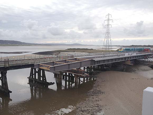
Opened in early April, the new replacement steel composite designed Loughor Viaduct has reinstated a double track rail service across the South Wales estuary, improving travel times between Swansea and Llanelli and boosting the local economy.
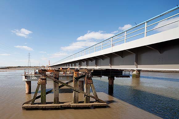
Originally constructed in 1852, the 236m long Viaduct was initially a wooden structure and a fine example of Isambard Kingdom Brunel’s once numerous timber viaducts.
However substantial redesigns and strengthening works in subsequent years had altered the bridge and most of the recently demolished viaduct dated from around 1910.
Importantly in recent times detailed site investigations had determined that the old viaduct had reached the end of its life and was no longer able to function and support the expected amount of modern rail traffic.
For capacity the double track bridge had been reduced to a single track, which proved to be inconvenient as the region still required a robust rail link over the estuary.
In order to improve rail services and restore the line to a double track configuration Network Rail, working with Carillion Rail, opted to replace the entire structure as part of a £48M scheme.
A primary consideration was how the new viaduct could be constructed within a limited 250-hour possession provided by Network Rail.
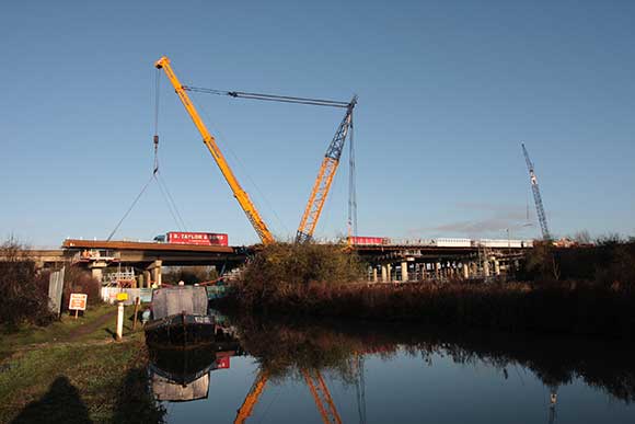
The new structure was slid sideways into the position of the old bridge
The bridge was launched in four individual sections
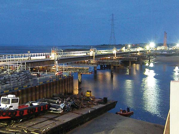
“Before commencing the steelwork on site we had to construct our temporary works and the new bridge piers in a high flow tidal estuary working from both sides of the existing viaduct,” says Jon Kite, Carillion Rail Senior Project Manager. “Our piling rigs and cranes worked from jack up barges in the river working between trains as necessary so as not to disrupt the operational railway.”
The work included the installation of twelve 1,200mm diameter permanent steel cased piles to form the foundations for the new viaduct.
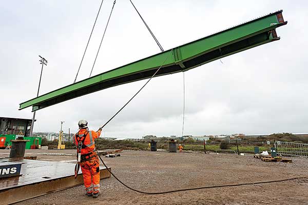
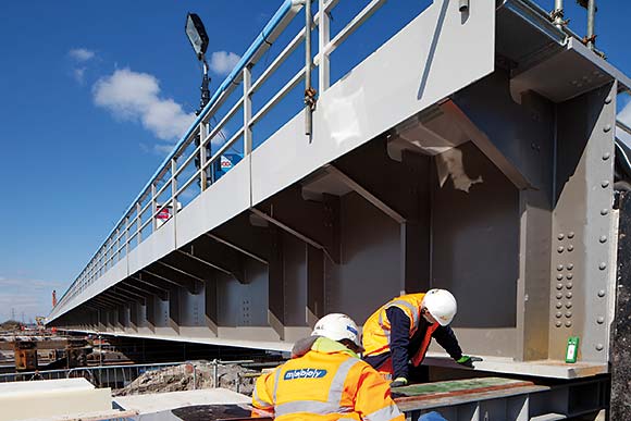
At the same time as this work was being undertaken steelwork contractor Mabey Bridge began a three month programme, fabricating the structural steelwork and walkways at its facility in Chepstow.
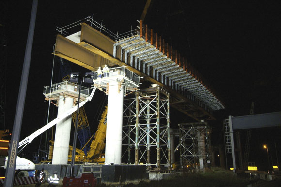
Mabey Bridge was also contracted to oversee site assembly, including the temporary pier cross beams to support the launch of the new structure. These beams were installed atop six temporary piers that had been installed on the north side of the existing viaduct.
The fabricated steelwork was transported to site by road in girder sections up to 24m long. The new bridge was then assembled in four sections in a laydown area on the west side of the estuary, ready to be launched alongside the existing viaduct.
To facilitate the launching process, the assembly area had previously been excavated and sheet piled, to ensure it was at the same level as the existing rail track and viaduct.
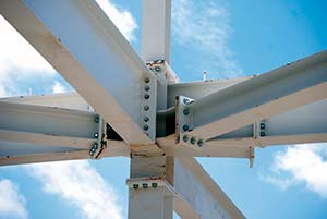
Space was at a premium and each of the four viaduct sections was assembled individually. Each section was a different length and consisted of two outer plate girders connected by a series of crossbeams. Steel walkways were also attached to each side of the structure. A total of 26 girders were needed (13 on each side) to construct the entire 236m long viaduct.
“Once the first section was fully assembled we launched it, using strand jacks, over the river onto temporary piers,” explains Roger Walker, Mabey Bridge Project Manager. “We then assembled the next section, bolted it onto the previous section and launched the structure a bit further over the river.”
This process was repeated a further three times, to position the entire new viaduct, spanning the Loughor estuary adjacent to the old existing structure. The steelwork was then jacked down onto its permanent bearings. The deck was concreted, waterproofed, ballasted and tracks laid.
The 250-hour rail possession was then initiated and work began to demolish the old structure. After putting protective rubber matting over the rail tracks, Carillion Rail used the new bridge as a working deck for its demolition equipment.
Once the old structure had been dismantled and new abutments constructed the new viaduct was slid sideways on its bearings to its permanent location using hydraulic rams.
After the viaduct opened one of Carillion Rail’s final tasks on site was to construct a heritage monument to reflect the old structure. Positioned on the west bank of the estuary, the monument consists of two of the original spans mounted on three of the original trestles.
“The monument captures an element of a unique structure in history that used early steel in its deck with support from timber trestles,” sums up Mr Kite.
Design and launch
 Mabey Bridge held a series of planning meetings with structural engineers Tony Gee & Partners and main contractor Carillion Rail to establish the suitability of steelwork for the launching and sliding process. Design discussions at these initial meetings covered the number of launches, nose and tail design, splice design and positioning.
Following agreement on design, Mabey Bridge began a three month programme of fabrication of the 1,200t of structural steelwork and walkways for the 236m long viaduct.
“The bridge has a total of seven spans, five of which are 36m long, this design was best achieved using steelwork,” says Chris Young, Tony Gee & Partners Regional Director. “Plus we had to have a soffit which mimicked the existing structure’s low profile for environmental reasons, again another reason for choosing steel.”