Projects and Features
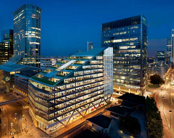
The Cornerstone Project: New Wellcome HQ Building

Fig 1: Site plan
The Wellcome Trust’s new headquarters building is currently under construction in central London. It will provide the Trust with 28,000m² of new office accommodation and enable it to consolidate all its administrative and public activities onto a single site. Andrew Woodward reports.
FACT FILE: The Wellcome Trust's headquarters
Architect: Michael Hopkins and Partners
Structural Engineer: WSP Cantor Seinuk
Fire Engineer: Arup Fire
Steelwork Contractor: William Hare
The site covers an area of approximately 100m by 36m and is flanked to the north by Euston Road, to the west by Gower Street, to the south by Gower Place and to the east by the existing Wellcome Building (fig 1).
An entrance to Euston Square underground station is situated in the north-west corner of the site and underground railway lines run in a shallow cut-and-cover tunnel beneath Euston Road.
Two levels of basement are provided beneath the building and these are waterproofed to achieve a Grade 4 environment to BS 8102 and CIRIA 139. The Grade 4 environment is achieved by a three-level protection system, consisting of:
- External tanking
- Concrete designed to resist water penetration
- Internal drained cavity
The basement will contain more than 20km of mobile racking and will house the Trust’s extensive collection of medical archives, books and paintings.
Frame
The new building is divided into a ten-storey block along Euston Road and a six-storey block along Gower Place. The two blocks are separated by a 9m wide atrium running the full length of the building.

Fig 2: Typical Floor

Fig 3: Section looking east
The north block floor plates comprise five 12 wide by 18m deep office areas linked by 9m wide ‘mini-atria’. Columns to each office area are positioned at the corners, at positions set back 4.5m from the front and rear edges, and mid-way along the perimeter beams (figs 2 and 3). Perimeter beam deflections are carefully controlled to meet criteria set for the cladding system. Secondary beams span 12 m across each block and are designed compositely with the lightweight concrete floor slabs.
The mini-atria are framed with a standard beam arrangement so that voids can be filled in or created at a later date.
The south block comprises compositely designed secondary beams supported on 9m long tapered plate girder primaries, which are in turn supported on columns spaced at 9m or 6m centres. The south block column layout matches the perimeter column grid of the north block.
In the north block, web openings of various shapes and sizes are provided in the primary and secondary beams to facilitate the distribution of services. In the south block distribution is carried out below the shallow 6m long secondary beams.
The steel columns of both the north and south blocks are supported directly off the top of the pile caps constructed below the sub-basement slab. Steel corbel brackets are used to support reinforced concrete basement and ground floor slabs. Between ground floor level and subbasement, the column sections are designed to act compositely with the concrete encasement.
The concrete encasement also provides the required two hour fire protection. Above ground, circular hollow section (CHS) columns are expressed both internally and externally. They are filled with plain concrete and designed compositely.
The CHS columns are joined at every second floor using site welded machined bosses. The fabricator, William Hare, added internal stabber guides to the tops of each boss to enable the columns to be bolted together in the temporary condition and allow the steel beams which frame into the column to be erected. The columns are lined and levelled, and welded to the connection boss. Then the temporary bolts are removed, all holes are made good and the splice is painted.
Link bridges and lift structures
At each end of the atrium, steel link bridges connect the north and south blocks at 1st through to 5th floor level. The link bridges are designed to provide the landings to adjacent banks of passenger lifts.

Fig 4: Link bridge structure and suspension system

Fig 5: Link bridge under construction
The link bridges are formed from stiffened steel plate, which acts as permanent formwork and supports reinforced concrete slabs. These floor slabs are supported on fabricated Tsection secondary beams which cantilever each side of twin primary beams. The primary beams are also formed from a fabricated Tsection welded to a circular hollow section.
Each link bridge is constructed in two parts, one 4.5m long the other 9m long. These separate parts are connected using exposed pins onto a plate girder which is suspended from a system of Macalloy tie rods. Diagonal tie rods located between the passenger lift shafts pick up the loads from the plate girders and transfer the weight back to the main columns.
Two further levels of link bridge are also suspended from this connection using vertical hangers (fig. 4). In the unlikely event of one of the diagonal ties within the lift shaft being damaged or removed each tie rod system is linked to the others with emergency ties.
Each level of link bridge is erected on temporary props which are supported on the concrete walls which form the lift pits (fig. 5). The link bridges are pre-set on the temporary props to take account of the extension of the suspension system. Fine adjustment of the level of each link bridge is carried out using turnbuckles incorporated into the tie rod end fittings.
Stability
The approach to stability was an important factor in developing an integrated engineering and architectural aesthetic. Stability of the north block in the east-west direction is achieved by providing pairs of cross-braced frames within the two mini-atria. The frames along Euston Road comprise high-strength tie rod bracing between independent CHS columns which are linked back to the floor plate at alternate floors. The frames along the atrium comprise high strength tie rod bracing between the corner columns described above.
Stability of the north block in the north-south direction is provided by bracing systems constructed between four pairs of columns in each floor area. These systems consist of flat plate cross bracing which is fire protected and designed to prevent collapse at the fire limit state (when deflection need not be controlled); they are also used to provide temporary stability to the frame during erection.
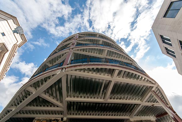
Cladding
The cladding in front of the cross bracing comprises stiffened steel panels. These panels together with the supporting columns are designed as vertical cantilever beams with the columns acting as the flanges of the beams and the stiffened steel panels as webs. The panels are bolted between the pairs of columns using high strength friction grip bolts and are used to control horizontal movement and satisfy the occupancy comfort criteria under serviceability limit state wind loads. As the panels only contribute to the in-service stiffness of the stability system they are not fire protected.

Fig 6: Thermally broken stiffened steel panel
Along the north elevation the external cladding is stepped back from the general office façade line at the mini-atria locations. This means that a part of the cladding formed from stiffened steel panels passes through the external envelope. At these positions, thermal breaks are formed in the steel panels to prevent cold bridging which would otherwise lead to condensation on the inside faces of the panels. The thermal breaks require the panels to be fabricated in two parts. The connection between the parts is made using bolts and spacers; the gaps are filled with insulation (fig. 6).
As mentioned above, the stiffened steel panels form an integral part of the stability system for the building and are used to control sway movements. While it is possible to derive the capacity of this system by theoretical calculation, a series of physical tests were carried out by Professor David Nethercot’s team at Imperial College to verify its structural integrity and more importantly, to determine its increased flexibility. The results of these tests were then fed back into the stability analysis model to enable the sway movements to be more accurately predicted.
The west end of the north block is detailed with a cross-braced frame similar to the stability frames in the east-west direction. The south block is stabilised in the east–west direction by a pair of cross braced frames along the atrium edge. Stability in the north–south direction is achieved by connecting the south block to the north block via the link bridges located at the lift core positions. These links also provide torsional stability to the south block. A cross braced frame is also provided at the junction of the south block and the existing Wellcome Building.
Fire protection
The building is over 30 m tall and therefore Approved Document B of the Building Regulations requires 120 minute standard of fire resistance. However a fire-engineered solution based on a ‘time-equivalent’ analysis carried out by Arup Fire showed that the fire resistance period for the typical office levels could be reduced to just 60 minutes.
A further fire engineering study based on the results of the Cardington laboratory full scale testing showed that the applied fire protection to the edge beams could be reduced to 30 minutes, resulting in a level of structural performance equivalent to the internal 60 minute protected structure.
The composite beams to the office floors are protected using intumescent paint applied at works which allows easy services installation though the web openings in each beam. The alternative, using traditional fire resistant board cut around holes, is expensive and time consuming. In the core areas where services pass below smaller beams, fire resistant board is used rather than intumescent paint.
The exposed CHS columns are protected using intumescent paint. Infilling the columns with concrete minimises the paint thickness. Small ventilation holes are provided at regular intervals over the height of the columns to prevent any build up of steam in the event of a fire.
The link bridges and their suspension systems are not fire protected. The main link bridge beams are sufficiently remote from significant fire load and the suspension system is shielded from any potential fire by the walls to the rear of the lift shafts.
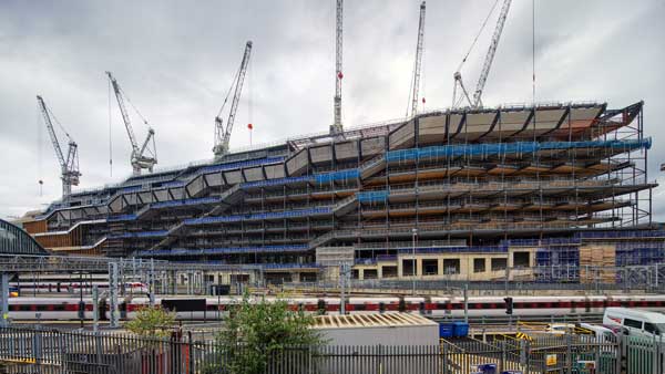
The substructure was completed in December 2002 and the steel frame was well advanced, with the cladding commenced in January 2003.
Andrew Woodward is a Technical Director of WSP Cantor Seinuk.