Projects and Features
Steel takes the load
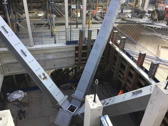
Both trees are similar in design and provide comparable structural solutions.
The London School of Economics’ new Marshall Building includes a number of steelwork elements that are helping the design to achieve the overall architectural vision as well as maintaining slimmer structural profiles. Martin Cooper reports.
FACT FILE
Marshall Building, London School of Economics
Main client: London School of Economics
Architect: Grafton Architects
Main contractor: Mace
Structural engineer: AKT II
Steelwork contractor: Bourne Steel
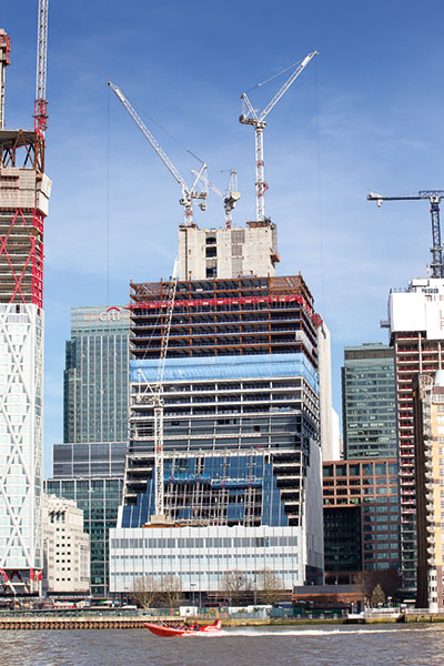
Steel tonnage: 126tOffering approximately 18,100m² of space, the Marshall Building is the latest project in the London School of Economics (LSE) campus-wide redevelopment programme.
Following on from the recently completed Centre Building (see NSC May 2018), the Marshall Building occupies a prime spot, overlooking Lincolns Inn Fields.
The new flagship building will have ten upper floors and two basement levels, and will contain The Marshall Institute for Philanthropy and Social Entrepreneurship, founded by Sir Thomas Hughes-Hallett and Sir Paul Marshall to improve the impact, effectiveness and appeal of private contributions to the public good.
It will also house the academic departments of accounting, finance and management, teaching facilities, as well as sports and arts rehearsal facilities including a Sports England standard multi-purpose sports hall for use by staff and students.
Overall the Marshall Building is a concrete-framed structure, but within its frame there are a number of integral steelwork elements, that have been introduced to provide the necessary structural capacity, achieve the desired architectural vision as well as to maintain slimmer structural profiles.
The trees form open plan areas within the building
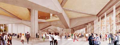
Visualisation of the completed interior
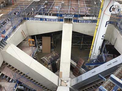
Once the steelwork was installed, the entire tree was encased in concrete
Tree two has a steel ring beam in order to create a void in the level four slab
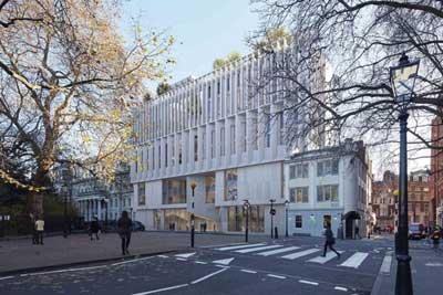
Visualisation of the completed Marshall Building
At level one, steel nodes have been installed to transfer loads into the core wall
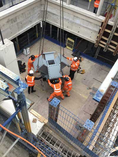
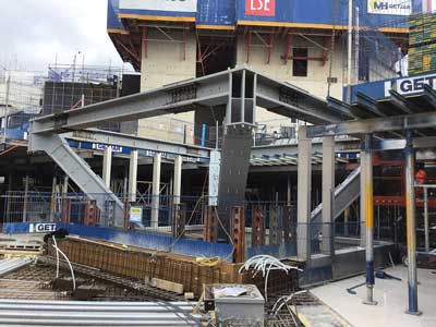
One of the tree nodes is lifted into place.
All of the steelwork will be hidden from view within the completed building, as it will all be encased in concrete to blend in with the adjacent structures. However, two of the most noticeable elements formed with steelwork are two tree-like structures, that help to create open-plan areas and evenly transfer substantial loads to the foundations.
Both of the trees have four steel raking branches, are similar in size and provide similar solutions. Tree one is supported by a column, stemming from the first floor through a second-floor void, and supports the third floor. Tree two supports the slab at level four and is founded on a steel column that is sat on top of a transfer beam at level one.
“Steel was used for the trees as the four branches collectively support approximately 3,500t, which was not feasible in concrete given the structural zones available,’ explains AKT II Associate Wai Pang.
“Steel was also chosen as the most suitable form of construction due to the concentration of load effect from raking columns.”
Tree one was delivered to site in six pieces, which consisted of a base plate, central node and four branches. Each of the branches weighed 8t and were fabricated from 700mm × 700mm × 50mm rectangular hollow sections (RHS).
The second tree supports the level four slab and is supported on an 8m-high, 10t column. It helps to form a central atrium within the Marshall Building.
Tree two came in ten pieces, which consisted of a column, central node, four branches and a ring beam. The branches weighed 6t each and were fabricated from slightly smaller 500mm × 500mm × 40mm RHS.
The architectural intent for this tree was to have a void in the slab at level four, and therefore it was not possible to have connecting Macalloy bars between the opposite raking branches, like the other tree. As the forces are lower, the design team decided to redirect the horizontal forces around the perimeter of the void with a steel ring beam encased in concrete.
“Coordination between the individual trades was key to installing the trees successfully,” explains Mace Senior Design Manager Richard O’Shea. “Our steelwork contractor, Bourne Steel, had to work in tandem with the concrete contractor, as the trees were erected within the concrete programme. Once the trees were installed the encasement was begun and the slabs were cast on top of them.”
The installation process for the first tree, sat at level two, had to wait until the slab was cast around the 2.5m² cast-in base plate. This then allowed Bourne to install the prefabricated node, which weighed approximately 5.5t. Once the node was bolted into position, using grout between the base plate and node for positional tolerance, each of the 7m-long branches were individually lifted into place and held in place with temporary bracings.
In a cross formation, a series of high-tensile Macalloy bars connect the tops of diagonally opposite branches. The bars were installed as each branch supports a column and, due to the large axial compression loads in the raking steel elements, a significant component of tension is introduced at the top of the tree system within the third-floor slab.
“The tension forces are resolved through a system of Macalloy high tension bars within the concrete floor,” adds Mr Pang. “Pre-tensioning the Macalloy bars during construction allows pre-compression of the floor slab, which reduces the risk of cracking in the floor slab during normal loading as the arms tend to splay apart under the building loading.”
“Lifting the tree steelwork into position and achieving the critical erection tolerances was a difficult task,” says Bourne Steel Project Manager Theo Pitrakkos. “The installation programme was very tight, the pit lane for offloading the steel has limited space and the site logistics simply did not allow for any storage. This meant that our deliveries and lifting operations had to be planned so the steel could be installed directly off the transport vehicle with minimal handling.”
High strength steel of grade S460NL was specified for the trees. This material had a long lead time, was a challenge to source within the programme constraints, and also required original welding procedures to be developed to suit the design requirements.
Bourne Steel Construction Manager, Steve Condon adds: “To safely erect the complex steelwork trees, we worked closely with the temporary works design team to strategically locate any lifting brackets, while also reviewing the connection details to ensure that the steel was erected within tolerance.
“We also trial erected both of the trees at our Poole fabrication yard, prior to delivering them to site, in order to make sure they could be assembled correctly.”
Elsewhere on the project, there are two steel nodes, each weighing 2t, which have been cast into the building’s main concrete core at level one. These triangular steel elements measure 1.5m × 800mm × 800mm.
They have been installed as concrete transfer beams at level one span up to 30m between supporting columns. These concrete beams act continuously over supports and the connection to the east core requires a continuous connection.
The resultant forces are very large and are required to mobilise the mass of the core to resist overturning. As the beams are set at 45 degrees to the core, the large tension forces must be translated into the walls on the orthogonal grid, therefore a steel node was provided to anchor all reinforcement and allow for the change in direction of the forces.
At the steel node locations, a combined system of standard reinforcement couplers and Macalloy bars have been used.
Bourne Steel’s design team adopted Finite Element Analysis to model both nodes, applying the loads at each of the individual coupler locations. This gave a good representation of how the nodes were behaving under the complex loading that they were subjected to. Furthermore, due to the unique structure of the nodes, determining a fabrication sequence that would allow adequate access to all of the welds was indeed a challenge.
Each of the nodes are supported on 3m-high steel columns. The columns are sacrificial and negated the need for temporary works during the node installation process. Later in the construction programme, they were cast into the concrete cores. Bourne Steel also supplied a base plate for installation at ground floor weighing 0.5t, measuring 1.5m × 1.5m with 1m long rebar welded onto one side.
The Marshall Building is due to complete in time for the start of the autumn 2021 term.