Projects and Features
Lift-off for feature roof

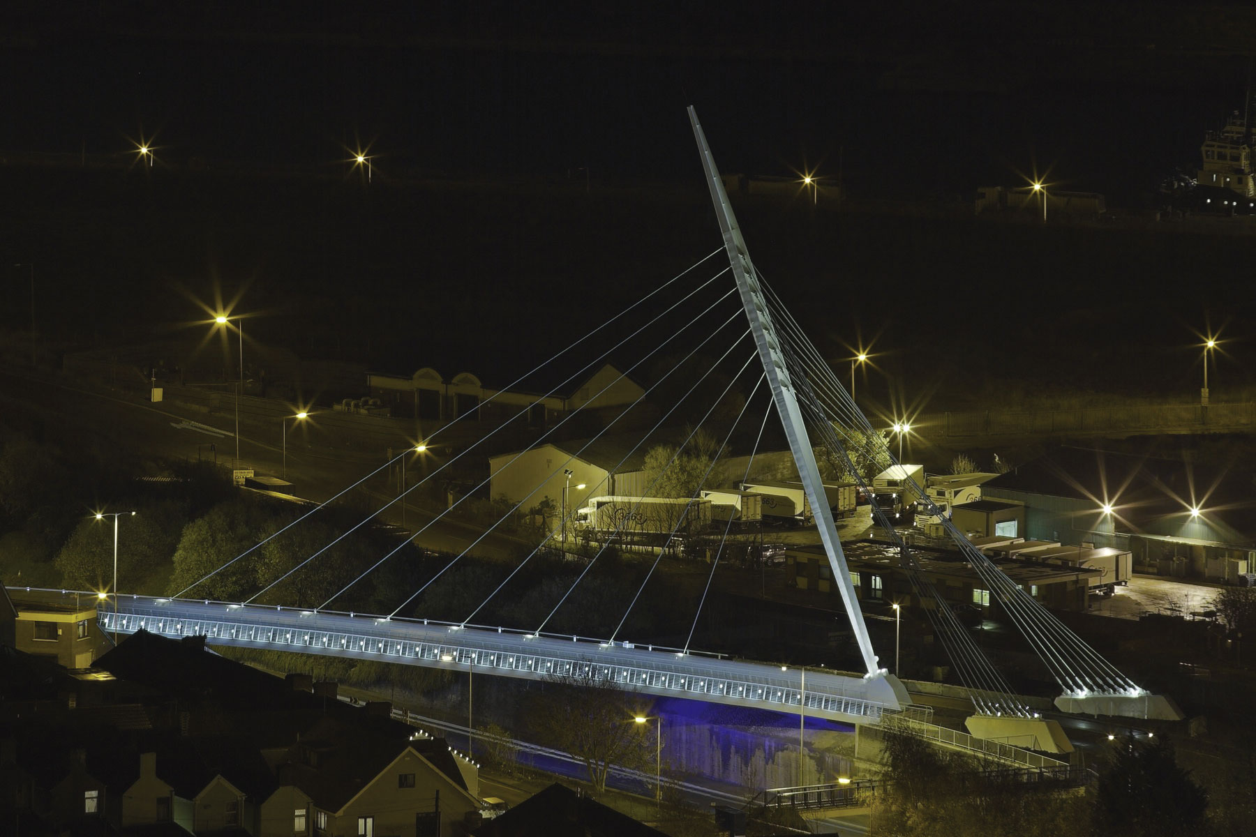
How the completed structure will look during the Games
The Aquatics Centre is one of the centrepieces of London’s Olympic Park. Martin Cooper reports on the erection of its elegantly sweeping and curving roof structure.
FACT FILE: Aquatics Centre, Olympic Park, London
Main client: Olympic Delivery Authority
Architect: Zaha Hadid Architects
Main contractor: Balfour Beatty Construction
Structural engineer: Arup
Steelwork contractor: Rowecord Engineering
Steel tonnage: 2,800t
Construction work at London’s 2012 Olympic Park has now moved up a gear or two as some of the larger structures begin to take shape. The main stadium is progressing on schedule with steel sections of the roof already in place, while nearby the first structural elements of the Aquatics Centre have also begun to be erected.
Designed by Zaha Hadid, the Aquatics Centre will mark the gateway to the Olympic Park during the 2012 Games and in legacy it will provide elite and community facilities that east London does not currently have.
The most eye-catching part of the venue is its complex steel roof. It sweeps upwards in a smooth curve from the south end and down again at the north, while the eastern and western tips curve upwards at the edges.
When complete, the 11,000m² roof structure will span a column-free area of 160m long and up to 90m wide. The roof will rest on two concrete cores 54m apart at the northern end, and a 28m long x 5m wide supporting wall at its southern end. The roof cantilevers 30m beyond its supports at the northern point while the two wings cantilever 27m on the sides. What this all means is, the entire roof will be supported on just three points.

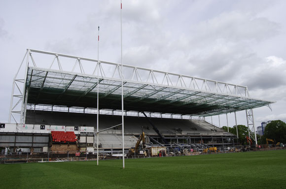
Steel trusses are supported on four rows of temporary trestles during construction

Steel sections are brought to site and assembled on the ground before being lifted into position

The initial primary truss being erected for the Aquatic Centre’s roof

All steel sections have been fabricated and delivered to site by Rowecord Engineering

3D image of the roof’s east elevation
There will be 2,500 seats inside a permanent building and a further 15,000 in two temporary structures on the sides. To enable spectators at the back of the temporary tiers to see the action, the roof has to be higher in the middle than at the edges.
Aside from the main steel roof, the temporary tiers, which will be removed after the Games, are also to be constructed with steel (rakers) while each of these side elements will have its own roof. Independent of the main roof, the two temporary roofs will require the erection of one large 85m-long truss each.
Structurally the system forming the main roof comprises a series of long span trusses over the main pool hall and these have a fan arrangement to create the plan geometry of the structure. The middle truss has a span of approximately 120m to a primary truss which in turn spans 54m in a transverse direction between the two concrete cores.
These centre fan trusses cantilever beyond the primary truss to form a 30m overhanging canopy at the northern end. The chords forming the trusses are facetted between truss node points with the purlins set at variable height off the trusses to produce the required roof curvature along the truss lines.
The trusses splay progressively outwards from the centre of the roof towards the edges like a fan. This supports the cantilevered wings at the sides as the trusses act like an inclined tied arch anchored by support points. The centre fan trusses carry the load over the central part of the roof in truss action. They are also supported by transverse transfer trusses taking the vertical load to discrete support points on the lower concrete superstructure.
Stability is provided by a system of horizontal and diagonal cross braces in the roof surface between the top chords of the fan trusses. The lower surface is braced up to the upper surface through lower surface horizontal braces and transverse diagonal bracing between the upper and lower surfaces.
Constructing the roof has not been helped by the site’s numerous constraints. It has a railway line to the east, a canal to the west and the future water polo site to the north. Two large tunnels housing the high voltage cables that were originally carried by pylons pass beneath the site.
“We wanted to simplify the roof as much as possible for construction,” says Mike King, Arup’s Project Engineer. “It’s a complex structure and the main structural challenge is the fact that it’s only supported at three points.”
To construct the roof while causing minimal impact on the overall programme the steel structure is being built in situ. The steel members are made from fabricated H-shaped sections by Rowecord Engineering. The initial steel section to be erected was a primary truss which sits on the south wall and supports the fan trusses that span the entire length of the roof.
“Early in the design process we did consider building the roof with timber,” adds Mr King. “However, it became apparent that the structure has too many high forces in its geometry, particularly where the fan trusses are thinnest.”
The first parts of the fan trusses began to be erected in April and are being fabricated in sections. These are then brought to site by Rowecord and craned into position. They are then held up by temporary trestles arranged in four rows between the south and northern ends.
This methodology was chosen as the best solution, although building the entire structure on the ground and then jacking it into position was considered. However, the roof’s curved shaped would have required just as many temporary supports.
The major benefits of the chosen erection sequence are that while the trusses are being erected the two northern cores are also being constructed. By the time the roof reaches the north end the cores will be complete. Also, by this time the southern or first line of support trestles will be dismantled once the roof gets to the middle point. This will allow main contractor Balfour Beatty to get started with the job of excavating the pool facilities.
When the steel roof structure is completed this Summer, the remaining support trestles will then be dismantled and to facilitate this the entire roof will be lifted up two metres at its southern end, turning on fixed spherical bearings at the northern supports.
Once all of the trestles are removed the 160m long roof frame will be lowered on to its permanent bearings at the southern end. Again, the entire roof will rotate about the northern spherical bearings when the southern end is lowered. Once this is complete, work will commence on the Kalzip standing seam roofing. Services will be fitted inside the roof void and timber cladding will be fixed to the underside of the structure next year.
Commenting on the structure, Architect Zaha Hadid says: “It is very exciting to see such progress on site. The roof reflects the fluidity of water and will provide an inspirational legacy for all Londoners well beyond the 2012 Games.”

How the Aquatic Centre will appear after the Games minus the temporary seating