50 & 20 Years Ago
50 Years Ago: An Evolutionary Building in London – The 26-storey Shell Centre
 From Building with Steel, August 1961
More than 6,300 tons of steel, rising from basement to roof, to a height of 389 ft., are contained in the tower block which dominates the scene of the new London headquarters of the Shell International Petroleum Company.
During the four years that have passed since construction work began on the seven-acre South Bank site of the old Festival of Britain, the Shell tower block has attracted considerable architectural interest.
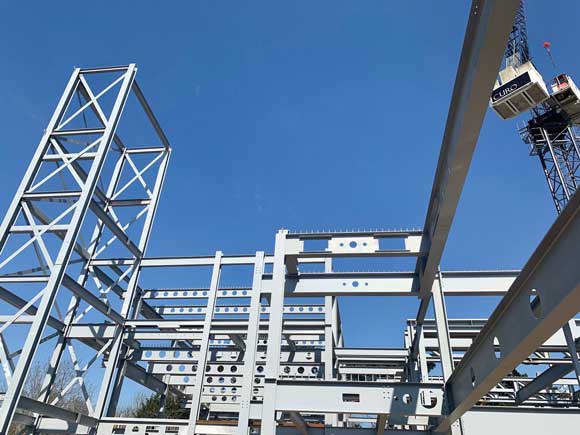
The building is a masterpiece of architectural skill and structural steel engineering. It is also the first modern fully air-conditioned tall building to be designed and erected in London: and some of the many lesson learned from its exacting design and construction programme, which had their origins a decade ago, has gone into the several other tall buildings which have since followed it up on the London skyline.
The tall tower block, with its low wings, was the architect’s compromise between his brief to provide accommodation on limited space for a staff of 6,000, and restrictions imposed by the London County Council designed to avoid disharmony with County Hall and other neighbouring buildings. The use of steel was dictated by necessity: without steel the building as planned could not have been erected.
The difficulties which had to be overcome were many.
RIGID BASIC REQUIREMENTS
Owing to physical limitations on the length and width of the building, both architectural and structural engineering planning had to meet rigid basic requirements and be contained in a specified plan envelope. After lifts, boiler flues and other essential services had been housed, the sizes of the columns had to be kept to the practical minima. The depths of the main beams were also restricted.
Exterior columns had to be shaped to allow flush interior faces to the main walls, which would permit easy adjustment of partitions and room sizes throughout the life of the building.
Because the battery of lifts had to be situated in a position eccentric to the main axis of the building and a large vertical shaft had to be incorporated to enclose three chimney flues from the boiler house, the building and framework could not be symmetrical. (The flues, it is interesting to note, are vertically self-supporting throughout the entire height of the building, receiving lateral support from the main steelwork.)
There were also severe restrictions on the amount and positioning of the vertical wind-bracing systems as is common in office buildings today: diagonal wind-bracing could be utilised only in certain of the transverse frames and was particularly limited in the portion below the second floor.
EXCEPTIONAL STRENGTH REQUIRED

Finally, dominating the whole situation, preliminary studies proved that to meet the needs of immediate and foreseeable future usage the structural elements must be designed to withstand superimposed loads appreciably greater than current British Standard minima.
A structural steel framework and a special ‘rigid frame’ design were seen as the means of overcoming these problems.
The structure was welded throughout, apart from site connections above the second floor. Site welding was used for the main frame connections up to the second floor level and high-strength bolt connections were used above this level.
The framework above the second floor rests on specially designed steel bearings which transfer the vertical load to the main portal frames. These frames were designed and constructed as two-storey, three-bay portals, of which the stanchions were welded box sections. certain of these stanchions were supplied with inner web plates and all were fabricated in one length of 70 ft., complete with haunches for site welding the joints to the portal beams at ground and second floor level.
The portal frames were interconnected longitudinally by main beams at the ground and second floors, with rigid joints to the stanchions to provide for the longitudinal wind forces in conjunction with the small amount of wind bracing next to the lift shafts. Stanchions in the lift and staircase areas were of welded I-sections.
RIGID FRAME
The steelwork above the second floor was designed to act as a rigid framework acting in conjuction with the wind bracing which consists of four panels within the 27-ft. 6-in. centre bay, and two panels 20 ft wide alongside the lift shafts. Virtually all stanchions are of welded I-section, the largest being 37 in by 20 in.
A special connection incorporating a welded haunch and end plate and using special grade 65/75-ton U.T.S. friction-grip bolts was developed for the fixed-ended main beams. It was subjected to full-scale testing before being put into use. In this part of the building, rigid connections were also used for the main longitudinal beams to provide rigid frame action against wind forces in this direction.
The main foundations for the tower had to carry loads of 2,900 tons including wind loads. To meet this need the consulting engineers evolved, and developed in conjunction with the contractor, large bored-pile cylinders of 7 ft. diameter and belled out to 15 ft. diameter at their lower end. The technique, based on oil-well drilling practice, proved successful and economical; it is an outstanding example of techniques evolved to meet the special problems encountered in the building and subsequently used to advantage in the later tall buildings. In all, 142 such shafts were sunk on the site, some to a depth of 120 ft below the surface. Forty-nine of these were under the tower block.