Technical
Guidance on Long Span Composite Floors
Mark Lawson of SCI reviews new guidance on the serviceability performance of long span propped composite floors prepared with NHBC.
Introduction
Composite slabs using profiled steel decking are widely used in all types of steel framed buildings and the decking is generally designed to be continuous and un-propped during construction. At the ultimate limit state, composite slabs are designed as simply supported but at the serviceability limit state, they are designed as semi-continuous. Spans of un-propped slabs are generally in the range of 3 to 4.5m. In recent years, there has been a demand to use this form of construction for intermediate floors in residential buildings, in which the slabs are physically discontinuous by their attachment to light steel walls and are often propped during construction. Spans of propped composite slabs are often in the range of 5 to 6m.
In long span propped composite slabs, it has been found that creep and shrinkage effects in the concrete can lead to higher deflections than in shorter span continuous slabs used in steel framed buildings. This is caused by the higher loads applied on removal of the temporary props and drying out of the simply supported slab from its top surface. The nature of construction process is also different from multi-storey steel framed buildings as relatively heavy construction loads, such as pallets of plasterboard, are often applied to recently concreted floors. It is very important that best practice should be followed in the way the decking is propped and props should not be removed before the concrete has developed adequate strength, which might otherwise affect the creep induced deflection.
The design of composite slabs is covered in BS EN 1994-1-1 (Eurocode 4) and, previously, in BS 5950-4. When these codes were developed, composite slabs were expected to be physically continuous and with spans of 3 to 4m. Therefore, guidance given on issues such as creep and shrinkage was relatively limited because it was less of a concern to the serviceability performance of these floors. However, when designing discontinuous composite slabs with spans up to 6m, it is important to ensure that the resulting deflections for this type of construction are within acceptable limits, particularly for residential buildings.
The following guidance note has been agreed with the National House Builders Council (NHBC), the Metal Cladding and Roofing Manufacturers Association (MCRMA) based on a study by The Steel Construction Institute. MCRMA is the trade body of the manufacturers of steel profiled decking.
Creep and Shrinkage Design to Eurocode 4
There is no effect of creep and shrinkage on the shear-bond performance of composite slabs at the ultimate limit state, and the only issue affecting design is the control of deflections over time. The nature of creep and shrinkage is that 90% of its long term effect occurs within 3 to 4 years of completion of the building when it is fully enclosed and heated. Therefore, deflections will stabilise over time and will not increase unless there is significant reduction in the relative humidity of the space.
For continuous composite slabs, there is no requirement to take into account shrinkage induced deflections according to Eurocode 4 clause 9.8.2(3). The effect of creep is allowed for by using an effective modulus of elasticity of concrete that is half of that of the secant modulus of elasticity. However, for propped composite slabs, the effect of creep is likely to be higher than that which is allowed in Eurocode 4, and in simply supported spans, shrinkage induced deflections will be higher because of the lack of continuity of the slab and its mesh reinforcement. Eurocode 4 makes a general reference to BS EN 1992-1-1: Eurocode 2 Annex B for guidance on the effects due to creep and shrinkage in reinforced concrete slabs.
Simple design approach
In order to address the question of the longer term deflection of propped composite slabs, SCI has developed simplified design rules in collaboration with NHBC which ensure that normal deflection limits for single span composite slabs are satisfied taking account of the long term effects of creep and shrinkage. The simple approach for scheme design is based on limiting the slab span to depth ratio. Two design cases are identified: In the first case, the slab is designed as a composite slab with or without bar reinforcement. In the second case, the slab is reinforced so that the profiled decking is considered to act as permanent formwork at the ultimate limit state. The maximum span to depth ratios for single span propped composite slabs according to the two design approaches are as follows.
(i) In case 1, where composite action is utilised at both the ultimate and serviceability limit states, the clear span to depth ratio should not exceed 28. It is assumed that reinforcing bars are placed in the ribs for fire resistance purposes. However, if no bars are specified (eg for 30 minutes fire resistance), then the span to depth limit for a single span slab should be reduced to 26 (this is because the slab will be less stiff without bar reinforcement).
(ii) In case 2, where no composite action is assumed at the ultimate limit state and the slab is fully reinforced, the span to depth ratio should not exceed 30, up to a maximum span of 6m (ie using a slab depth of 200mm). The bar reinforcement included in the deck ribs should be designed in accordance with Eurocode 2 or BS 8110. However, for acceptable serviceability performance, the cross-sectional area of the composite decking may be included in combination with the reinforcement when calculating the composite stiffness.
The depth of the slab is taken as the overall depth of the floor. In both approaches, steel mesh reinforcement should be provided in the topping. This reinforcement should be not less than 0.2% of the cross sectional area of the concrete above the ribs. For continuous slabs that are propped in construction, the minimum area of steel should be increased to 0.4% of the cross sectional of the concrete above the ribs in accordance with Eurocode 4 clause 9.8.1(2).
Detailed design approach for single span propped slabs
SCI recommends the following procedures for the detailed design of single span propped composite slabs in accordance with Eurocode 4. This is necessary so that proper account is taken of creep and shrinkage effects in the concrete:
1. The long term elastic modulus for concrete should be taken as one-third of the short term value for the calculation of self weight deflections and other dead load deflections due to the loads on de-propping, i.e. an elastic modulus of 10 kN/mm² or a modular ratio of not less than 21.
2. The average of the cracked and uncracked stiffnesses (EI values) of the composite slab is used in the calculations, including the effect of steel bar reinforcement in the ribs.
3. For the calculation of deflection due to imposed loads, the deflection may be taken as assuming 2/3 of the applied load is a short term load and 1/3 is a long term load.
4. The minimum imposed load in residential buildings should be taken as 2.0 kN/m² to reflect the possibility of higher loads during construction.
5. Shrinkage induced deflection should include a minimum free shrinkage strain of 325 microstrain. A simple formula for shrinkage induced deflection of a composite slab is:
0.105 × Shrinkage Strain × Span squared/Effective slab depth
This formula takes account of the stiffening effect of the mesh reinforcement placed in the slab topping which reduces the theoretical shrinkage induced deflection by about 20%.
6. The total deflection of the slab top surface taking account of creep and shrinkage effects should not exceed 24 mm or span/250, whichever is less. If shrinkage effects are ignored in the calculations, then the total deflection should not exceed 16 mm or span/375.

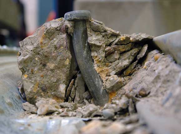
Figure 1: Load test on a 5m span composite floor slab using water filled bags
Comparative design studies show that the results of these calculations are compatible with the above simplified rules. These design limits should not be unduly conservative in relation to the typical spans specified in residential buildings.
They do not apply to continuous composite slabs where span: depth ratios can be higher. In un-propped slabs, it is the spanning capabilities of the decking in construction that is usually critical and creep effects are much less than in propped slabs.
The short term deflection and vibration sensitivity of composite floors in not affected by creep and shrinkage. A load test on a 5m span composite floor of only 150mm depth conducted by NHBC gave a deflection of only 6mm under an test load of 1.5 kN/m² – see Figure 1. This is consistent with the short term composite stiffness and showed that the composite action is satisfactory.
For more information, contact Mark Lawson at SCI m.lawson@steel-sci.com
Correction
In the July/August 2011 Technical Article on Member Buckling with tension flange restraint, two formulae were incorrectly copied from the Eurocode.
In example 1, the expression for NcrT was given as
![]()
where is2 = iy2 + iz2 + a2
This should have been
![]() , where is2 = iy2 + iz2 + a2
, where is2 = iy2 + iz2 + a2
The numerical values calculated in the article used the correct formulae.