Technical
AD 307: Additional Moments in Braced Bays: 2
This is the second AD in a series that comments on the forces and moments to be designed for in beam-column-bracing connections in braced frames. AD 306 covered the 3 most common cases which should be used where possible. This AD covers a further 3 connection details which are frequently employed and offers advice on how they can be designed.
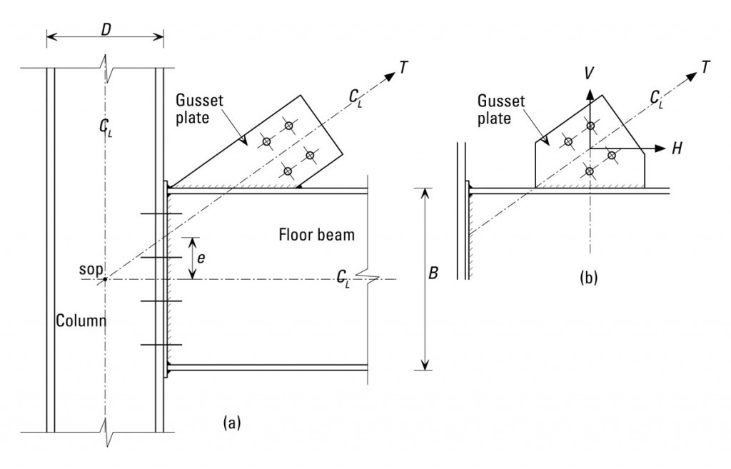
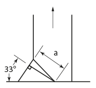
Figure 1 shows a situation, with two alternative gusset plate details, that arises due to the inclination of the bracing member when the centre lines of the members are coincident. Although the gusset is only attached to the beam this arrangement should be designed as the first case in AD 306 using either of the models described therein. Alternatively, the designer may rearrange the whole beam-column-bracing detail in accordance with either the second or third cases as described in AD 306 and design appropriately.
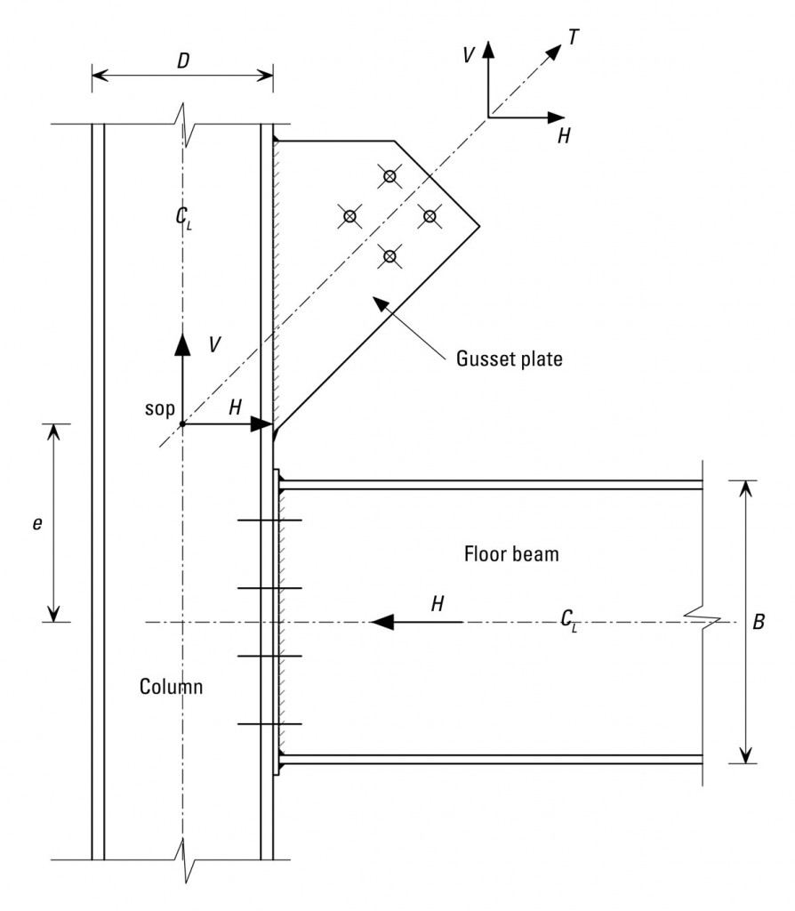
In order to create an alternative simple detail to Figure 1 the gusset plate may be attached to the column separately as shown in Figure 2. In this case the horizontal component H of the brace force causes additional bending of the column. The bending moment diagram caused by this effect may be determined directly from the structural analysis if modelled appropriately but in hand calculations it is usual to take an additional moment, M = He on the column.
This is a primary moment acting on the column and not a nominal moment and is therefore not to be distributed into the column above and below the joint as described in clause 4.7.7 in BS 5950-1: 2000. The column should be designed for the primary moment as well as the nominal moment from the beam end reaction in accordance with section 4.8.3 of BS 5950-1: 2000. Refer to AD 275 for guidance on the design of columns in simple structures and special design cases.
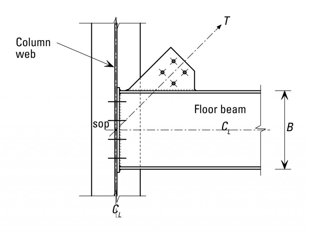
The arrangement shown in figure 3 is commonly used when the floor beam in the braced bay is attached to the column web. In this case it is usual to assume that there is no additional moment from the brace force on the column or connection due to the thickness of the column web. The vertical shear through the connection is the beam reaction plus the vertical component of the bracing force. The column is designed for the nominal moment due to the assumed eccentric reaction of the beam shear.
In summary, when additional moments arise in braced bays due to the location of the setting out point they must be added to the usual nominal moments from the beam end reactions and accounted for in the design of the column and its splices. Moreover, the gusset plates in both AD 306 and AD 307 are shown subject to tension only. A further AD will offer advice on the design of gusset plates subject to both tension and compression.
Contact: Thomas Cosgrove
Email: t.cosgrove@steel-sci.com
Tel: 01344 636555

