Projects and Features
Steel allows access to all areas
 Six weeks have been shaved off a vital construction programme by changing a podium design from concrete to steel. Martin Cooper reports.
FACT FILE
Pancras Square, King’s Cross, London
Main client: Argent
Architect: Townshend Landscape Architects/BAM Design
Main contractor: BAM Construction
Structural engineer: BAM Design
Steelwork contractor: Fisher Engineering
Steel tonnage: 600t
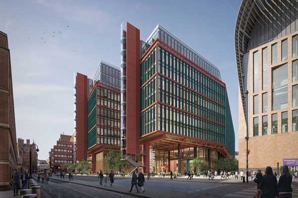
Pancras Square forms an important part of the huge King’s Cross development that is radically changing a former rundown industrial site in central London into a new and vibrant neighbourhood.
Also known as Zone B, Pancras Square will eventually consist of seven commercial and retail buildings situated around a central public square. Future tenants already include BNP Paribas Real Estate and Camden Council.
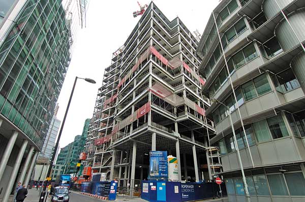
To facilitate the construction of these buildings, five of which are currently in various stages of development, a 4,000m² podium is being formed. When the project is complete this large steel structure will provide a shared delivery basement for all buildings as well as the level platform for the landscaped public realm. During the construction phase it importantly creates a robust two level (basement and level one) working surface for the project’s many project teams.
 “The main driver for this project is speed of construction as we had to provide construction access for the adjacent buildings, via the basement of the podium, by 23 December and via the podium top by March,” explains Mick Kelly, BAM Construction Project Manager.

The speed of constructing the podium with steel has allowed work on adjacent sites to start on time
The podium is in fact the catalyst for the rest of the Pancras Square project and in order to achieve these important deadlines the choice of materials was crucial.
“Originally the design was for an insitu concrete structure, but it would have been too slow and the amount of formwork needed would have restricted access below the podium and to the surrounding building sites,” explains David Carter, BAM Design Director.
“We changed the design to a steel frame supporting precast planks as this is the fastest method and the best way of meeting our deadlines. Using steel we’ve actually saved at least six weeks on our programme.”
The Pancras Square site was previously one of Europe’s largest gas works, and consequently a large amount of remediation work needed to be carried out before the construction phase could kick off during May 2012.
Once piling was complete Fisher Engineering was able to begin its steel erection sequence. The contract also included the installation of all the concrete planks, and the entire task was finished in just seven weeks.
The podium site is hemmed in on all sides by other construction projects, and with little or no room to manoeuvre the erection sequence had to be phased.
“We also had to coordinate our programme to allow vehicular access to some of these sites via our working area,” explains Glen McCleery, Fisher Engineering Project Manager.
Little or no storage space was available to Fisher Engineering, so steelwork arrived on site in a just in time basis, to be erected almost immediately.
Adopting a sequential approach, Fisher Engineering gradually worked in a south to north direction along the podium length. Once the planks were installed on top of the steel, the structure was ready for the asphalt topping to be applied, which then meant the top of the podium was ready to be used.
The steelwork programme was so quick and efficient that before the job was completed at one end of the site, the other end of the podium was already in use for material storage on the top deck and for vehicle access on the lower level.
To accommodate large trucks and the utilities that serve the buildings, the basement level of the podium has a 9m floor to ceiling height.
“Forming 9m high columns in concrete would have filled the site up with formwork and would have hindered the follow on trades and the necessary speed of construction,” says Mr Kelly.

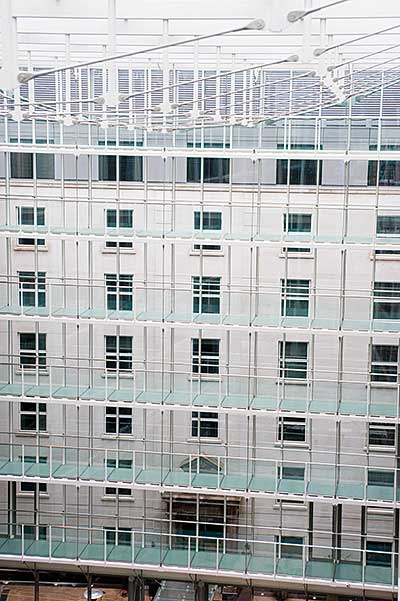
The podium will link into each of the surrounding commercial block’s basements
As the lower subterranean level of the podium will ultimately be used as a delivery yard for the surrounding buildings, it has to have large open column free spaces big enough for trucks to turn around in. These areas will also initially have to accommodate large construction vehicles from the adjacent sites.
“There are some long spans, up to 18m in places, and steel beams were the best way of forming these,” says Mr Carter.
The 18m long members are huge fabricated plate girders, up to 1,500mm deep. They not only form the necessary basement spaces, but they will also have to support some heavy loads on the podium’s top level. This will consist of construction traffic, the loads associated with the building of the realm and finally the public square itself.
The northern end of the site is approximately 3.5m higher than the southern end. The steel braced frame incorporates this slope via a series of steps which are located along the structure.

A steel frame supporting precast planks was the quickest construction option
At the step locations BAM designed (and Fisher Engineering fabricated) a series of plate girders and deep beams with a double lip configuration. The large steel elements accept 200mm deep planks on one side at a midpoint stiffened shelf plate, while on the other face the planks sit on the the top flange, thereby creating the step.
Greenery in the future public realm will include a number of trees and large shrubs. To accommodate the trees large prefabricated pits have been installed within the podium’s upper slab. These were formed in a similar fashion to the steps. However, shelf plates and top flange angles were only required where the step was greater than 200mm. Otherwise, where the step was 200mm the planks were supported onto the previous slab and then rested on the top flange of the steelwork that was higher.
“Many of the girders are very deep and so the pits didn’t need to be hung from the steelwork, they are supported by stiffened plates welded to the middle of the beams and angles welded to the bottom flange,” says Mr McCleery.
Steelwork erection and the installation of the precast planks were completed last October, which helped BAM meet its first deadline in December. The project team is now on schedule to meet the March date, when 40% of the upper level will be handed over to another contractor that will use it to enable construction of an adjacent building. They have use of the podium for 15 months, after which it is handed back to BAM to be landscaped, with the rest of the podium, creating Pancras Square, which is scheduled for completion in late 2014.
King’s Cross is being developed by the King’s Cross Central Limited Partnership, which brings together Argent King’s Cross Limited Partnership, London and Continental Railways Limited and DHL Supply Chain.
Connections for heavily loaded grids
Dr Richard Henderson (SCI)
 In circumstances where particularly heavy loads are to be supported and speed of construction is an essential project requirement, steel plate girders are an obvious solution. The podium of the Pancras Square project has been designed for such loads which include the following: 200mm thick precast concrete planks and 1500mm of insitu concrete topping and full HA loading. The design also includes 25 tree pits.
The plate girders span 18m and are 1500mm deep with 50mm thick flanges. The webs are designed as unstiffened. Secondary beams frame into the plate girders and these have been detailed for speed of erection. At the connection points, the plate girders have been provided with a tee stiffener which projects to the toe of the flanges. This allows the secondary beam to be dropped into place between the primary beams without having to negotiate their flanges to make a web connection.
The connection at the end of the secondary beam is designed for a shear force equal to the design reaction and a bending moment prescribed by the design reaction acting at the face of the tee. The tee stiffener is welded to the web and flanges of the plate girder to transfer the reaction to the plate girder web.
In general, when connecting primary and secondary beams, three options can be considered.
 Option 1: The secondary beams can be assumed to span from grid to grid and be provided with notched ends (if the primary and secondary beam flanges are at the same level) and a flexible connection to the primary beam web. The bolted connections can then be designed for shear only.
- Option 2: (as described above), the bolted connection can be moved to the edge of the flange and the connection designed for shear and a prescribed moment (see illustration).
- Option 3: The span of the secondary beams can be assumed to start from the edge of the primary beam flanges and the beam provided with flexible end connections designed for shear only. The reaction force must then be transferred to the primary beam web as in Option 2 and the resulting bending moment (torsion about the axis of the primary beam) suitably dealt with. This could be achieved by arranging for the moment to be transferred into a concrete slab supported by the primary and secondary beams. Option 3 requires agreement between the steelwork detailer and the designer of the structure that suitable means have been included in the design to deal with the torsion.