Projects and Features
SSDA 2011 – Other finalists
The Point, Lancashire County Cricket Club

FACT FILE: The Point, Lancashire County Cricket Club
Architect: BDP
Structural engineer: Capita Symonds Structures
Steelwork contractor: Watson Steel Structures Ltd (Severfield-Rowen Plc)
Main contractor: Morgan Sindall
Client: Lancashire County Cricket Club
Lancashire County Cricket Club’s vision, for the Point development at its Old Trafford ground, was to build a 1,000 seat hospitality and banqueting venue, while also providing over 2,500 new stadium seats.
The requirement for space and height drove the unique design, which has put the events space above the new spectator seating creating shelter, unimpeded spatial flexibility and a spectacular full height glazed wall.
The use of steel was the only way such a demanding structure could have been delivered economically given the short construction programme and site constraints, says Capita Symonds. The high load capacity of steel meant that the cantilever elements could be kept as compact as possible, with steel exposed and expressed to suit the architectural requirements.
The terrace seating is formed from raking steel beams supporting precast concrete units. Above this, the second level events area cantilevers 12m over the stadium terracing and was constructed using a series of eight fabricated plate girders.
The girders are radially aligned with the terrace grid and varied in depth from 600mm deep at the cantilever tip to 1,200mm deep at the head of the raking columns.
Above this, a series of plate girder roof beams were designed to accommodate the services, folding partitions and roof loadings. These spanned 26m from the pitch side CHS columns to the rear of the structure, incorporating service openings to suit the M&E needs.
New South Bridge, A406 Hanger Lane

FACT FILE: New South Bridge, A406 Hanger Lane
Structural Engineer: Hyder Consulting Ltd
Steelwork contractor: Cleveland Bridge UK Ltd
Main contractor: Vinci Construction UK Ltd
Client: Transport for London
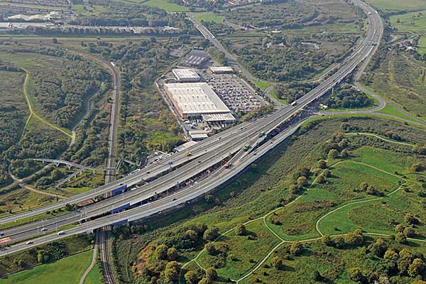
The New South Bridge is a replacement structure spanning two London Underground lines and four Network Rail tracks near the Hanger Lane roundabout in west London.
Steel was the automatic choice for the bridge, says Hyder, in order to span 45m, build it off -line and then manoeuvre it into place. Other benefits included a reduced weight, resulting in smaller and shallower caisson foundations.
Box girders for the bridge were fabricated in three small transportable sections, at Cleveland Bridge’s yard and then welded together on site to form the 45m span. The cross girders were bolted to the box sections with non-slip tension control bolts, which allowed accurate assembly of the trapezoidal plan shape of the bridge. The box girders were 3.4m high × 1.05m wide with depth haunching to 4m at the supports.
In order to avoid disruptive track possessions the fully assembled bridge was moved from its adjacent assembly yard by Self Propelled Modular Transporters (SPMTs) that launched the structure into place.
The launch procedure comprised a two stage operation with an initial counter clockwise 90 degree turn to position the bridge to the railway tracks. This was then followed by the main push southwards to carry the structure across the railway tracks.
Two lines of SPMTs were used to enable the whole bridge to be driven and pushed into place. To span the distances, the bridge had a temporary nose at the front and a 7m long temporary tail section to accommodate counter weights. The total weight of the launch structure, including the temporary sections, was almost 1,050t.
Riverside Waste to Energy Plant, Belvedere

FACT FILE: Riverside Waste to Energy Plant, Belvedere
Architect: Jacobs Engineering UK Ltd
Structural engineer: Jacobs Engineering UK Ltd
Steelwork contractor: Bourne Steel Ltd
Main contractor: Costain Group Plc
Client: Cory Environmental Ltd
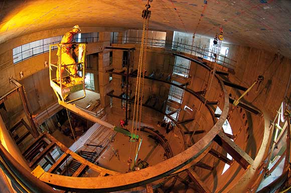
The UK’s largest energy from waste plant has been constructed on the banks of the River Thames at Belvedere. Known as the Riverside facility it will process more than 585,000t of municipal and commercial waste per year, and provide 66MW of electricity to the local grid.
The structure covers an area of over 13,000m², with its curved wave-form roof rising to a height of 55m. The main frame, internal plant supports and walkways were all erected using structural steelwork, which enabled the building to be constructed to its optimum height while also maximising internal space.
“The key to this project was integration,” explains Nick Hayes, Divisional Director for Bourne Steel. “We, as well as all the other sub-contractors, had to work around each other. In some areas steelwork was erected first, but in other sectors the equipment was installed first and we then had to come along and thread the steel columns, some 30m long, between large pieces of processing kit.”
Much of the steelwork was erected on top of concrete walls, such as the waste bunker where 20m long steel columns extend the building upwards to connect to the steel roof.
All of the steelwork used for the project’s frame was galvanised for durability. This process required one of the largest galvanising baths in the UK to accommodate some of the large truss sections.
The roof was one of the most challenging aspects of the project and all of the 36m-long cellform beams which form the roof were trial erected. This ensured the correct geometry could be achieved, as there is no constant radius.
Newport Station Regeneration, South Wales

FACT FILE: Newport Station Regeneration, South Wales
Architect: Grimshaw Architects LLP
Structural engineer: Atkins Ltd
Steelwork contractor: S H Structures Ltd
Main contractor: Galliford Try
Client: Network Rail
The regeneration of Newport’s railway station has been successfully completed with a futuristic design which boosts capacity and passenger comfort. Finished in readiness for last year’s Ryder Cup, the station features ticket facilities and platform access split equally between the two terminals, and these along with a linking footbridge are housed within continuous ETFE and aluminium clad spirals.
The use of an ETFE wrap over a steel structure not only creates a very bright and airy space but also, due to the lightness of the material, the structure requires minimal support.
Chris Pembridge, Atkins Regional Director, says this was one of the reasons why steel was chosen as the main framing material. “We looked at timber and concrete for the terminals but went for steel for its ease of construction as well as it lightness. The footbridge on the other hand was always going to be a steel structure because of the spans and its ability to achieve the organic form we were seeking.”
Linking the two terminals and allowing access to a central pair of platforms, the bridge has three spans and gains its stability from a central support containing a concrete lift core. The span from the north terminal to the central core is 23m, while from the south the span is 29m. The reason for this disparity being the bridge’s organic curving shape. A third, and much shorter span allows access, from the middle of the bridge and liftshaft, to the central staircase leading to the platforms.
Steelwork contractor SH Structures fabricated and then delivered the bridge decks to site in six sections.
By assembling as much of the footbridge as possible and then lifting completed sections into place the contractor minimised working at height and reduced the need for further rail possessions.
Bridge GE19, East London Line

FACT FILE: Bridge GE19, East London Line
Structural Engineer: Benaim
Steelwork contractor: Mabey Bridge Ltd
Main contractor: Balfour Beatty-Carillion Joint Venture
Client: Transport for London
Bridge GE19 is an 84m-long, 8m deep truss bridge which carries two lines of the new East London Line over the railway tracks originating at nearby Liverpool Street terminus.
Working above these ‘live’ railway lines was only permitted during weekend and Bank Holiday possessions and so the entire structure was pre-assembled in an adjacent goods yard.
Steelwork forming the deck was made up of ten longitudinal beams measuring between 20t and 24t, and 31 × 9m-long cross girders each weighing 4t. In total the bridge required Mabey Bridge to use 880t of steel and a further 140t for a temporary nose section which was removed once the structure was in its final position.
Once the entire bridge and its nose had been assembled it was moved to its final position by two self-propelled modular transporters and then jacked (launched) over the ‘live’ rails onto its furthest abutment. The entire launch was completed during one weekend rail possession.
“This bridge, because of its length had to be a warren truss,” explains Richard Selby, Mabey Bridge Head of Projects. “During the design we had to include all the movement stresses associated with the launch.”
In order to reduce the need for future maintenance on the structure, Mabey Bridge fabricated the bottom chords from weathering steel, as this would require no protective coating before installation – thereby saving the client money.
Museum of Liverpool

FACT FILE: Museum of Liverpool
Design Architect: 3XN Architects
Delivery architect: AEW Architects
Structural engineer: Buro Happold
Steelwork contractor: Caunton Engineering Ltd
Main contractor: PIHL/Galliford Try
Client: National Museums Liverpool
Delivery architect: AEW Architects
Structural engineer: Buro Happold
Steelwork contractor: Caunton Engineering Ltd
Main contractor: PIHL/Galliford Try
Client: National Museums Liverpool
Located on the banks of the River Mersey, the National Museum of Liverpool has been dubbed the ‘fourth grace’ following on from the historic the Royal Liver Building, Cunard Building and the former offices of the Mersey Docks and Harbour Board.
It is a striking building, a low, stone and glass-clad structure with sweeping “wing” roofs and huge glass picture windows at either end. On plan, it occupies the space of a partially closed X, and is symmetrical about the diagonal axis.
“It’s a very complex, unconventional form,” explains Buro Happold Structural Engineer David Taylor. “The client was looking for large, open spaces, and the architect has come up with a scheme which provides this, and within a very unusual form.”
The clear spans are at their most significant on the second floor, where there are two 40m long, column-free main galleries – one at either end -with the steel beams above spanning 28m across the width of the structure.
There is a total of 2,100 tonnes of steel in the building’s main structure, which has been designed to resist not just self-load and the weight of exhibits and visitors, but also the substantial horizontal and uplift forces from the high winds that affect the Mersey’s shores. All of this load is taken into the ground via a 4m deep reinforced concrete raft structure, consisting of top and bottom slabs joined by a series of vertical walls.
Buro Happold’s structural design splits the building into three sections – the centre and the two ends – with movement joints separating them. The split is necessary as there is the possibility of differential thermal expansion across the length of the structure. Although vertical forces can be transferred across the joints, the frame has been designed to ensure horizontal and rotational movement is contained within each section.
North Stand Redevelopment, Leicester Tigers

FACT FILE: North Stand Redevelopment, Leicester Tigers
Architect: AFL Architects
Structural engineer: WRS Corporation Ltd
Steelwork contractor: Caunton Engineering Ltd
Main contractor: Galliford Try
Client: Leicester Football Club Plc
Leicester Tigers, arguably Rugby Union’s best supported team, has an ambitious 10-year programme to redevelop its Welford Road ground into a modern 30,000 seat stadium complete with a raft of facilities
The first phase of the programme has been completed and involved the construction of a new 10,500 seat north stand, which has increased the ground’s capacity from 17,498 to 24,000.
During the 2008/09 season the new stand’s roof, including a 108m long king truss, as well as the upper portion of the stand where erected above the existing stand. This then allowed the old stand to be demolished, clearing the ground for the lower level of the new stand to be infilled.
The new stand’s footprint is much larger than the old stand and steelwork contractor Caunton Engineering was able to erect the majority of the new structure without impacting on the existing stand.
Two 1,000t capacity mobile cranes were positioned at either end of the stand to lift the roof truss into place. The crowning glory of the new structure, and visible for miles around, the roof’s 108m-long truss is 35m high x 12m deep and was delivered to site in more than 140 separate pieces. It was assembled on the ground and then erected in one tandem lift.
The roof’s cantilever is formed with Westok beams erected in three sections. Caunton erected the middle 6m section with the truss, and once the truss was in place it was then tied into the back of the stand with further 31m long Westoks. The front portion of the cantilever roof was later erected with 14m-long cellular beams.
Supporting the roof truss are two 24m high support pylons, prefabricated from tubular sections and delivered to site in one piece. These were erected prior to the truss lift.