Technical
Use of fibre-reinforced concrete in composite slabs (part 2)
Recent years have seen increasing interest in replacing the reinforcement mesh with steel fibres in composite slabs on steel decking. The drivers are largely economic, while the reduction of construction material suggests decreases in the carbon footprint may be possible. Along with reduced waste on site and less labour demand, the use of fibres makes a case for being more environmentally friendly when compared to using steel mesh reinforcement. Nevertheless, certain technical and practical issues should be considered when wishing to use fibres in concrete. In this second of two articles, Constantinos Kyprianou of the Steel Construction Institute reports on the design and construction considerations on the use of steel fibres mixed in concrete instead of conventional mesh reinforcement for a composite slab on steel decking.
Design of composite slabs with steel fibres
By testing
A common approach is design assisted by testing. The basic premise is that the performance of one metre wide composite slabs is representative since composite slabs on steel decking are always one-way spanning slabs. Such an approach has been adopted for almost 20 years ago by the Steel Construction Institute (SCI) for specified combinations of steel fibres and decking, and has been used principally to complement design with BS 5950.
By adapting conventional reinforced concrete design and using a mechanics-based approach
A simple approach adopted by some fibre suppliers is to firstly carry out a conventional design and then replace the area of mesh reinforcement with an equivalent (in terms of tensile capacity) amount of fibre while keeping the slab thickness unchanged. The required dosage of fibre is determined using standard bending theory such that the fibre-reinforced cross-section has the same post-cracking moment resistance as the mesh-reinforced cross-section. Similarly, equivalent tensile strength is used to determine the dosage needed to satisfy the minimum reinforcement requirements of the standards for crack control and longitudinal shear resistance for composite beams.
Flexural capacity can also be calculated using a plastic design approach, as described in TR34[1]. This approach is adopted by SCI to determine the moment resistance in fire when designing with the Eurocodes. This new method allows for more flexibility in design, and acts as an evolution of the approach previously developed by SCI for use with BS 5950. It should be noted that although in principle the methodology is simple, its implementation necessitates significant computation because of the iterations involved to calculate the required stress blocks. Therefore, it is almost always necessary to implement this method within software.
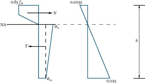
For the axial tensile strength of a flexural member the strength at CMOD 0.5 mm and 3.5 mm are considered, these are σr1 and σr4 respectively, and in accordance with TR34[1] are taken as:
σr1 = 0.45fR1
σr4 = 0.37fR4
where, fR1 and fR4 are defined in the first article.
These strengths are used to determine the cross-section resistance.
Fire design
Composite slabs at the normal stage are typically designed as single spanning, even when the deck is continuous over supports and designed as such at the construction stage. For typical UK practice, with no bars in the troughs, this means that the only reinforcement considered in design is that provided by the decking, which enhances the sagging moment resistance. Any hogging resistance provided by reinforcement, or fibres, is ignored. It is only during the accidental fire situation that the presence of mesh, or fibres, is recognised. SCI has produced a method using a plastic design approach of stress blocks to allow the tensile resistance of steel fibre-reinforced concrete (SFRC), deck and potentially bars in troughs to be considered in the determination of hogging and sagging resistances at elevated temperature. The methodology for considering the effects of SFRC is similar to the one described in TR34. Figure 1 shows the stress blocks to be considered for a typical flexural element with SFRC only, of which σr1 and σr4 are the tensile forces of SFRC.

For a fire scenario, a model for calculating concrete, deck and reinforcement temperatures is described in NCCI PN005c[2]. Based on these elevated temperatures, reduction factors are applied to the compressive strength of concrete and tensile strengths of SRFC, deck and bars in troughs (if present). Reduction factors are taken from the relevant Eurocodes, while for SFRC suitable factors have been determined by SCI based on the codified properties for concrete and reinforcement.
It should be noted that, as with conventionally reinforced slabs in fire, when the slab is physically single spanning (i.e. no end continuity), then a bar in trough is always required. When the slab is physically continuous over a support, this continuity is recognised in design and a semi-empirical rotation capacity check over the supports is performed to ensure that the continuity can be relied upon. A lack of rotation capacity could result in premature fracture of tensile components.
Considerations at the normal stage, ultimate limit state
Bending capacity
Typical composite slab design, at ambient temperature, ignores any tensile contribution from SFRC. The calculated shear bond parameters, τu and m & k, which are determined from full scale tests are assumed to be unaffected by the presence of fibres. The deck is considered to act compositely in (typically) partial interaction with the concrete, as external reinforcement.
Vertical shear
Currently in EN 1994[3], the vertical shear resistance of a composite slab only considers the role of the concrete, even though this appears conservative in ignoring any enhancement from the deck. The presence of steel fibres in concrete enhances its shear capacity; this is described in detail in the RILEM report[4] and TR34[1]. In current design this effect is conservatively ignored.
Punching shear
A punching shear resistance check is needed in the presence of a concentrated load. Punching shear resistance is partly provided by two cross-sections of the slab that run parallel to the slab span – the tensile reinforcement for these sections is provided by the decking (not mesh), as for vertical shear. Additional resistance is provided by two cross-sections that run perpendicular to the span of the slab – the tensile reinforcement for these is traditionally provided by mesh but can be provided by fibres.
Longitudinal shear – beam check
Satisfying the longitudinal shear resistance, which is a composite beam check even though the reinforcement is associated with the slab, requires a minimum area of transverse reinforcement to be determined in accordance with EN 1992-1-1 Clause 9.2.2 (5)[5]. A strut and tie model is used to determine the minimum area of reinforcement. This may be converted to an equivalent tensile force and compared to a resistance using SFRC.
Considerations at the normal stage, serviceability state
In accordance with EN 1994-1-1 clause 9.8.1 (2)[3], for continuous slabs that are nevertheless designed as simply supported the cross-sectional area of the anti-crack reinforcement above the ribs of the deck should be not less than 0.2% of the cross-sectional area of the concrete above the ribs for un-propped construction, and 0.4% of this cross-sectional area for propped construction.
For fibre design the required area of mesh reinforcement is converted to an equivalent tensile force, which is then used to determine the appropriate fibre dosage.
Construction and design considerations
Advantages
The main benefits of replacing mesh reinforcement with steel fibres are:
- Improvement in impact resistance and fatigue endurance.
- Improved durability of slab as a result of reduced cracking.
- Test evidence of SFRC enhancing the fire resistance of composite slabs [6,7].
- Reduction in construction time since it removes a trade.
- Reduction of site waste with unused mesh reinforcement.
- No issues associated with displacement of conventional mesh within the depth of the slab and clashing with the studs.
Savings in the cost of supplying and fixing conventional mesh reinforcement can offset the extra cost of adding fibres to the concrete. There may also be health and safety benefits resulting from the reduced handling of reinforcement.
Issues
Some of the issues that could arise with the use of steel fibres are:
- No standing platform for labour (which mesh offers) when pouring concrete, so care should be taken by workers not to damage the steel deck during pouring. Designers are advised to consider an extra construction-imposed load allowance to cover the direct contact with the deck.
- If the steel fibres are not already in a ready mixed concrete when delivered to site, care should be taken to ensure their effective mixing and even distribution during pouring. It can be difficult to control and check the even distribution of fibres. Although offsite mixing is associated with high quality control, contractors and suppliers should ensure that every effort is made for checking the quality of the pour and the even distribution of fibres in the concrete mix during construction of the slab.
- Admixtures such as superplasticisers, water reducers and hardeners may be needed in the concrete to aid with the even distribution of fibres within the concrete mix, and its fluidity, since the presence of fibres can act as a thickening agent.
- The finished surface will be rough because of protruding fibres, and will need additional screed if a smooth surface is needed.
- At the decommissioning phase of slabs, it can be extremely difficult and expensive to separate steel fibres from the concrete mix and re-use them. Similar, if not less onerous, issues exist as those currently faced by the construction industry for concrete-based structures at the end of their life.
Final comments
Although the use of steel fibres with composite slabs is nothing new, uptake is expected to rise as economic and sustainability drivers push this approach forward. With an experienced contractor and ready-mix concrete provider, the benefits can far outweigh the issues. In design, if by testing is not adopted, a mechanics-based methodology implemented within software provides a practical alternative.
References
- Concrete Society, 2018. Concrete Industrial ground floors, 4th edition. Technical Report No. 34.
- SCI, 2012. PN005c, NCCI: Fire resistance design of composite slabs.
- BSI, 2004. EN 1994-1-1. Eurocode 4: Design of composite steel and concrete structures —Part 1-1: General rules and rules for buildings.
- RILEM, 2003. TC 162-TDF, Tests and design methods for steel fibre reinforced concrete, σ-ε design method, Material and Structures, Vol. 36, pp. 560-567.
- BSI, 2004. EN 1992-1-1. Eurocode 2: Design of concrete structures —Part 1-1: General rules and rules for buildings.
- Fike, R. and Kodur, V., 2011. Enhancing the fire resistance of composite floor assemblies through the use of steel fiber reinforced concrete. Engineering Structures, 33(10), pp.2870-2878.
- Bednář, J., Wald, F., Vodička, J. and Kohoutková, A., 2013. Experiments on membrane action of composite floors with steel fibre reinforced concrete slab exposed to fire. Fire Safety Journal, 59, pp.111-121.


