50 & 20 Years Ago
The new Coventry Swimming Baths
 Reprinted from Building with Steel Volume 4 No. 3
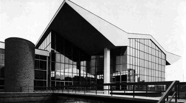
August 1966 These splendid new swimming baths are now in full operation: a number of interesting design features are incorporated in the structure, one being the ‘wish-bone’ system which permits full deflection of the roof structure without transferring any load to the vertical glazing.
The new baths replace the ones destroyed by bombing in 1940 and have been designed to fit into the general pattern of the new modern City centre, which includes buildings of advanced design, the adjacent Lanchester College of Technology being a notable example. In addition to the normal function of a swimming bath this Centre provides a first-class social environment in which it differs drastically from earlier baths. For instance, gardens and sun bathing terraces are attractive features and amenities such as a restaurant, games room and spectators’ galleries are included.
The building is in two parts, one housing the main swimming pool and adjoining, another containing two smaller pools, the restaurant and various rooms. Each has a steelwork superstructure and roof. A bed of rock some 6 feet below the site has been used to support the basement floor. The mass foundations under the stanchions supporting the roof structure over the main pool are also taken down to rock: elsewhere the building is supported on 17-in. diameter bored piles.
 The Main Pool Section
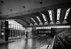
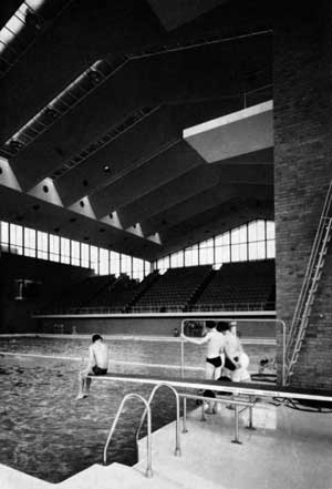
The whole roof (165 ft by 196 ft) of the main pool section is supported on four stanchions on a 155-ft by 112-ft rectangular grid. Between each pair of stanchions 155-ft lattice girders straddle the pool, and trusses, generally at 16-ft centres, span the 112 feet between the lattice girders and cantilever out from the girders a further 42 feet at each end. The roof covering is supported at 8-ft centres on purlin frames between the trusses. Framing for roof lanterns and internal lay lights is made integral with the purlin frames and at both south and north ends, the purlin frames are extended beyond the end trusses to carry fascia framing.
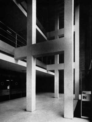
The four stanchions, two lattice girders and two end trusses are designed as portal frames in two directions and constitute a highly indeterminate but rigid structure. When analysing the stresses of this structure the fabricator used a computer. The stanchions, each weighing about 22 tons, are compound sections composed of two 24 in by 9 in by 94 lb universal beams with two 34 in by 17/8 in flange plates riveted to them.
High Yield Stress Steel
In the case of the two 45-ton main lattice girders the top and bottom booms are of high yield stress steel and consist of one 20 in. by 7½ in by 89 lb rolled steel joist with two 14-in flange plates of varying thickness: the internal members are of mild steel. To facilitate erection they were delivered piece-small and framed up on the ground at site, in the vertical position, all site joints being made with high strength friction grip bolts.
The main trusses between the lattice girders were shop welded in halves and the centre splices then site welded. Each leaf truss is a parallel flanged lattice girder approximately 11 ft deep and 56 ft long in plan, set to give a slope of a little less than 1 in 2 to that part of the roof. Springing from the same show level as the main trusses are the 42-ft cantilever trusses. These are arranged so that the rafters slope inwards from the cantilever end at about 1 in 30 and then pass over the tops of the main lattice girders to meet the rafters of the main trusses about 14 ft beyond the lattice girders. Gutters 2 ft 6 in wide are formed at this junction. The roof structure is completely braced against the effects of wind loading.
Except for the seven stretches of wide lantern lights between the main trusses the roof is covered with aluminium decking on 1-in thick cork insulation and three layers of roofing felt. An acoustic ceiling is provided by perforated aluminium strip with a rock wool backing.
The window mullions to the south side are composed of 1/16 in sheet steel formed into 18 in by 6 in box sections. The bases to the mullions are pinned and as mentioned earlier, the caps are hinged on a ‘wish-bone’ system.
The Small Pools Section
The roof steelwork for the small pools section consists of trusses 4 ft deep at the shoe, with rafters sloping at 1-in-24 from shoe to ridge so that surface water drains into the eaves and valley gutters. These trusses are 65 ft span over the small pools, 32 ft span over the games deck and 48 ft span over the entrance block and generally are at 16 ft centres. At the south side they cantilever 8 ft beyond the stanchion line to carry fascia frames. Purlin frames similar to those in the main pool section carry the roof decking. The underside of the roof steelwork is 28 ft 6 in above the poolside for both pools: interposed over the teaching pool is the restaurant floor which is carried on 33 in deep universal beams spanning 40 ft between two plate girders of 56-ft span.
On the east side (i.e. west side of main pool) the glass walls of the two sections are 3 ft apart and linked by a transverse glass panel set in 4 ft from the south elevation in which the glass walls to both blocks are in line. An expansion joint is incorporated into the details at the junction of the two blocks.
The baths were designed by the City Architect, Terence Gregory, ARIBA, ARICS, AMPTI: the structural design was carried out by the City Engineer, Granville Berry, MICE, MIMunE.


