50 & 20 Years Ago
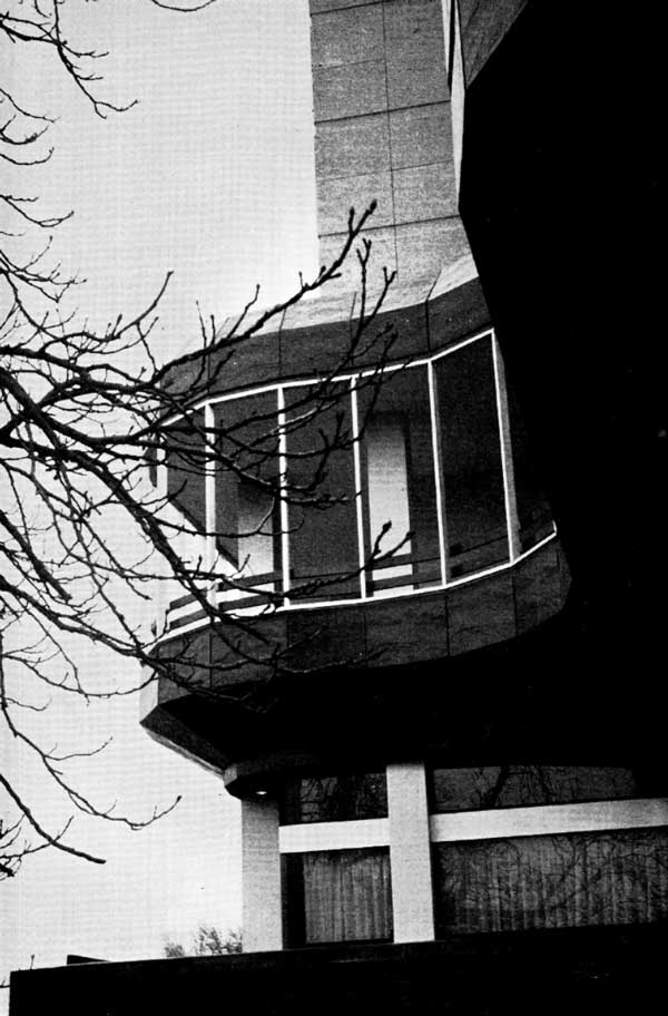
The County Hotel, Bedford
From Building with Steel, June 1969
by Gwylon Isaac, Bsc, DIC, CEng, MICE
In December 1964 the contractors appointed to carry out the construction of the hotel were at the very early planning stages of the project which was to be located on probably the most picturesque site in the centre of Bedford. At this stage in the development the only ray of sunlight was the location of the site – all other factors were a source of concern.
The site was a congested one hemmed in on all four sides by a bridge, a road, a river and a car park.
The geology of Bedford is such that great variations in soil and rock exist in a very small area. The author had himself experienced, over the years, gravel, blue clay and shale in the locality.
The Bedford County Hall affair had spotlighted the area and all eyes were focused on it.
The structure was likely to have three different architectural layouts to suit hotel public rooms, hotel bedrooms and flats on the top four storeys.
It was of vital necessity to erect the building as quickly as possible in order to open the hotel and relieve pressure on capital.
It was a period when labour was difficult to obtain and prices were rising rapidly.
These prevailing conditions and financial requirements thus called for a building which:
- Was fabricated mainly offsite and assembled with a minimum of labour.
- Would be erected quickly with no loss of time due to unavailability of labour or delays caused by inclement weather.
- Would easily and simply accommodate the change in plan layouts at the changeover floors.
- Would be as light as possible in order to overcome any possible difficulties with the, then unknown, site conditions.
- Would be trouble free in erection as the site was a feature in Bedford and visible for miles around.
During this preliminary period, a seven storey block of flats was being erected in Bedford in a semi-industrialized building system in which special precast concrete floor slabs are monolithically keyed to a steel frame in such a manner as to provide complete composite action. The nature and progress of this project attracted the interest of the main contractors for the hotel and resulted in the serious consideration of the adoption of the same system. And this was in spite of the fact that the contractors had their own highly competent reinforced concrete design subsidiary and that the existing architect’s drawings were based on a reinforced concrete concept!

It was obvious that, provided the system produced a satisfactory answer in economic terms, it would be adopted as the framing for the fourteen story structure since it met the contractors’ and the developer’s requirements in all other respects. A cost exercise was carried out on the existing plans in sufficient detail to produce a realistic figure for frame and floors. This figure, apart from changes in structure due to detail design, eventually turned out to be within 10 per cent of the final figure and it showed clearly that the system concerned was an economically viable proposition.
The contractors’ fundamental requirement of economical, speedy, offsite fabrication was being realised and the concept of precast composite construction and precast concrete cladding was the basis of all architectural engineering and contractual thinking during the detailing stage of the job. As far as the professional consultants were concerned items such as concrete mixers, scaffolding and carpenters were non-existent.
The frame
The structural steel frame consists of beams, designed compositely by the load factor method, carried on columns subject to vertical loads and moments caused only by eccentric connections. In other words the beam to column connection was assumed to be a pin.
This form of construction requires two additional structural elements to prevent collapse, namely, horizontal and vertical bracing. In this case the solid floor ‘studded’ to the beams provided the horizontal membrane, while diagonal steel elements provided the vertical bracing. The latter proved to be a problem as it was not possible to maintain a continuous vertical plane of bracing in any one position because of the changing plan requirements. In fact, the bracing panels were dispersed all over the structure.
While the bracing might appear to be haphazard, it is a carefully calculated element based upon the ‘storey box’ principle. This principle considers each storey as its own box in space, each box having a rigid lid and bottom. The box is subjected to a horizontal load at the lid and an equal horizontal reaction at the bottom, the horizontal load increasing in magnitude towards the lower storeys in the usual manner. Each box is vertically braced to withstand the horizontal forces from above. As a result of this distribution of vertical bracing brought about by changing plan form, nearly all the columns were subject to wind loads as the vertical reactions had to be carried down to the foundations eventually. The 25 per cent overstress allowed, however, ensured that only in a few cases were the column sizes increased because of wind. The horizontal deflection of the structure due to wind was restricted to 1 in 500 of the height. The calculation of the actual deflection was so linked with intangibles that only an approximate assessment could be made, and this was based on the following assumptions:
- The wind was blowing normal to one surface and only one plane of bracing was operative.
- The external cladding and internal partition contributed nothing to the overall stiffness.
- The wind load was distributed to the bracing in the inverse proportion of the column centres of the braced bays.
- The individual braced panels were assumed to be vertical cantilevers.
- Only the tension diagonal was assumed to be acting.
All the above assumptions were on the safe side with the exception of item 4. It was assumed, rightly it seems, that any error in assumption 4 would be more than outweighed by the other safeguards.
The fundamental requirement of the above reasoning is a floor acting as a horizontal membrane capable of transmitting wind loads to all the braced panels and the precast flooring used was specially developed so that, acting compositely with the steel beams, it would fulfil this function.

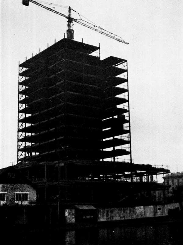
Erection
The erection technique was perfectly simple. The columns and beams for a complete shaft length, usually three storeys, were erected, lined, plumbed and levelled, and permanently braced. Temporary bracing was required for each lift of steelwork until the permanent bracing could be fixed. The floor slabs were then lifted into position by the steelwork erectors and the jointing carried out by the general contractor. By the time the jointing was complete, the steelwork for the next lift had been raised on to the top floor. This was then erected and temporarily braced by guy ropes and the preceding sequence of events repeated. Because the completed floors had permanent bracing in position, temporary bracing was needed only for the lift actually being erected and erection was always progressing from a firm base under which the general contractor was proceeding with the builder’s work. It was also equally advantageous to the steelwork contractor to be able to work off a clean and exclusive top floor.
Although it was found necessary to store some of the steelwork on site, it was possible to arrange deliveries of the flooring units so that they could be lifted directly from the lorries and placed in position. This saved double handling and avoided further congestion on a restricted site.
A tower crane, located in the lift well inside the building, was used for raising all components. The crane was tied back at the fifth and ninth floors to the skeleton frame which, in withstanding the consequential twisting forces, provided ample testimony to the innate strength of this system of construction.
Cladding, internal partitions and fire protection
The concept of completely dry construction was not pursued in the matter of internal partitions. These were of lightweight concrete blocks faced with plasterboard. The steelwork, to conform with the Bylaws which existed at the time, required external weather protection and internal fire resistance. In each case the column or beam was located inside a hollow cavity, the walls of which were either the external cladding or the internal lining. In this way a separate item for ‘casing’ was avoided. In practice, this technique resulted in the inner face of the inner skin lining up with the tips of the column flanges. The necessary thickness of plaster for fire protection of the steelwork was placed over expanded metal. Beams were invariably located on one side of a partition, so that only one side and a soffit had to be separately cased. All these details were produced as a result of close liaison between engineer, architect and contractor. The capacity of the tower crane and the radius of lift limited the size of the external cladding panels. These were of waffle construction in the interest of lightness and were basically of 2½in thick slab, faced with ¾in Cornish granite in white matrix and stiffened with ribs. These ribs also provided fixings to attach to the steel frame. All the cladding was fixed from inside the building. The only work requiring access to the outside face was the joint sealing operation and this was carried out from the window cleaning cradles.
The foundations
The site investigation showed that, beneath a variable thickness of made ground and alluvium approximately 16ft thick, lay a bed of oolitic limestone. This bed was proved for a thickness of 17ft. Unfortunately it was discovered to be fissured and at 3ft below its surface a 6in thick clay band was encountered. As the column loads in some instances would be 400 tons, it became vitally important to know the true nature of this limestone.
Two alternatives were available. The upper crust of rock could be penetrated and large diameter piles could then be founded on bedrock, with the strength of the concrete controlling the load on the pile, or the foundations could be on the top layer of rock, using a pressure of 20 tons per sq ft, provided rock existed to a minimum depth of two pile diameters before any clay fissure was encountered. The problem resolved itself into the adoption of 19in diameter piles carrying 40 tons at the top of the rock or 80 tons at some undefined depth below the top. There were hazards connected with either of the solutions but the one which appeared to have greater control on costs and time was the 40 tons pile at high level. It was necessary to prove the rock for both schemes and only when necessary would there be any excavation in the rock to form 80 ton piles.
The rock proving was carried out by a 6in coring rig, rock cores being taken out between the 16ft and 25ft levels. Eighteen such cores were obtained and each core exhibited the fissuring to varying degrees. It became apparent that the clay was really decomposed or soft rock of considerable shear strength and in a confined area could carry an ultimate load of 15 tons per sq ft. On this basis and assuming a factor of safety of 2, it was considered safe enough to accept a minimum 2ft thickness of limestone under the pile. Another consideration in reaching this decision was that in no instance was there more than 12in of clay in the top 5ft of rock and settlement of such a narrow band would be of no consequence. Subsequent tests on two of the working piles showed complete recovery after test loads of 60 and 70 tons respectively.
Acknowledgements
The developers were J. M. Hill & Sons (Ampthill) Ltd and the architects were Ronald Salmon & Partners, A/ARIBA, A. J. Middleton, AADipl, ARIBA, being the partner in charge of the project. The author was the consulting engineer. The structural system was designed by Prestressed and Reinforced Concrete Engineering Ltd.