50 & 20 Years Ago
Fabricating the Irwell Valley Bridge
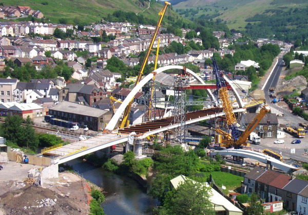
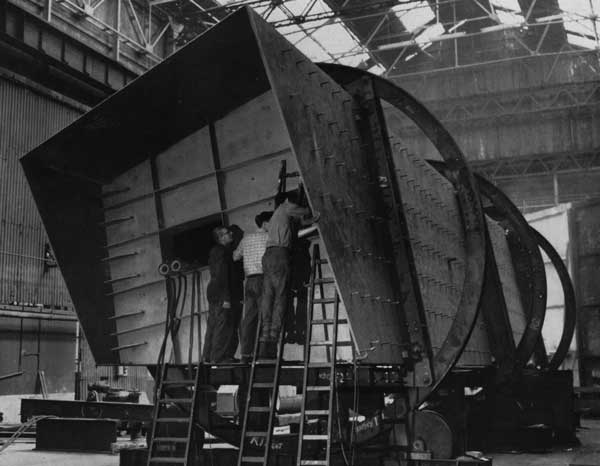 The Irwell Valley Bridge is a single span road bridge, over 200 ft long, comprising seven trapezoidal box girders. Each girder was fabricated at the works in four parts. This is a good example of steel prefabrication and the various processes involved in the shop fabrication are well illustrated in the accompanying photographs and drawings. Each girder was fabricated so that when finally positioned on site it had a camber of 21/8 in. The two middle sections of the girder are each 45 ft long and weigh 36½ tons, whilst the two outer sections with their skew ends are each 64 ft long and weigh 46 tons. The box girders are 10 ft 10 in deep, 12 ft wide at the top and 8 ft at the bottom. The web plates are ½ in thick throughout but the flange thicknesses vary as follows: the middle sections have top flanges 1 in thick and bottom flanges of 2 in plate; the corresponding thicknesses for the end sections are ¾ in and 15/8 in. The flanges for the end sections are made from two plates butt welded together but the middle section flanges are in single plates. The bottom flanges in all cases are of NDII steel to BS.2762.
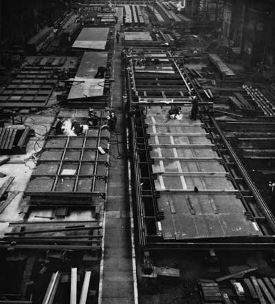 Material preparation and assembly
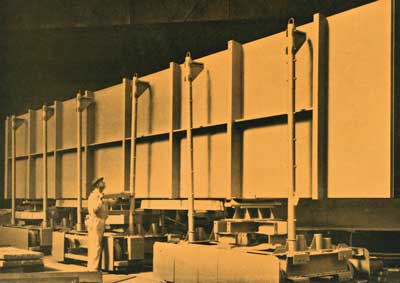
All web and flange plates were flame cut to width and bevelled as required, in one pass, on a specially constructed double-headed burning bench. Indicators were incorporated to enable the plates to be marked to length. Longitudinal and transverse stiffeners, 6 in bulb flats and 7 in by 3½ in by 7/16 in angles respectively, were sub-assembled to webs and flanges in assembly jigs.
All flange stiffeners were welded in with 5/16 in fillet welds on both sides and web stiffeners were similarly attached with 3/16 in fillet welds. Two welders worked simultaneously, one on each side of a stiffener, working from the centre outwards, to ensure that all the welds were balanced and to avoid distortion. After sub-assembly, all parts were blast cleaned and given one coat of etch primer.
Final assembly
For the final assembly of each section, a former jig was used to keep the webs and flanges firmly in position and at the same time kept the ends in the correct relationship. As a further aid to assembly, holes were drilled in the transverse angle stiffeners so that the webs and flanges could be tack bolted together: the holes were filled with galvanized bolts before the inside of the box was painted. To ensure that on site the ends matched, an inside former frame was also used to maintain the correct shape and overall dimensions of the ends of the boxes. The assembled box was strongly tacked before being transferred to the manipulator jig for final welding. Weld details were modified at the corners of the boxes to give a more balanced weld and to allow the two corners to be welded whilst the box was in one position, ie with the web horizontal, thus saving a part turn.
Additionally, the edges of the bottom flanges were bevelled in line with the web to avoid a shadow line on the bridge.
Non-destructive testing
All plates were ultrasonically tested in the works and shop butt welds in both top and bottom flanges were subject to 100 per cent radiographic testing. In addition, coupon plates were provided for further testing of these butt welds, the tests being: one tensile, one normal bend, one reverse bend for each flange, with three charpy ‘V’-notch tests for the tension flange. The latter were carried out, with the notch in the weld metal vertical to the plate surface at -15°C and the requirements for NDII steel to BS.2762 in this respect, ie average value of 20 ft lb for three specimens with no individual specimen breaking under less that 15 ft lb, were fully met. The other mechanical tests were conducted in accordance with BS.709.
All inside fillet welds on tension flanges were tested for cracks using K-07 Magnaflux simplified crack detector with Ardrox No 800-2 black magnetic particle inspection, kerosene based.
Tests for welding procedures
All welders were required to pass the appropriate tests specified in BS.2645 according to the degree of skill necessitated by the procedures, manual, semi-automatic, or automatic, on which they were to be employed.
The Irwell Valley Bridge was designed by Lancashire County Council and the contract was placed by the MoT North Western Road Construction Unit (Director, Mr James Drake, CBE).
Reprinted from Volume 5 No. 3
July 1968