SSDA Awards
SSDA 2003 – New Hangars for TAG Farnborough Airport

Part of the £45m redevelopment of TAG Farnborough Airport, which also includes a 35m high air traffic control tower and brand new terminal, the £9m three bay hangar is 290m long, 45m deep and 22m high at the apex and large enough to accommodate six Boeing 737s.
FACT FILE: TAG Farnborough Airport
Structural Engineer: Buro Happold
Steelwork Contractor: Rowecord Engineering
Main Contractor: Bovis Lend Lease
Client: TAG Farnborough Airport
TAG Farnborough has a vision for the airport and seeks to differentiate themselves from other service providers in this field through the design and quality of the facilities it provides. The challenge set for the design and construction team of REID Architecture, Buro Happold and Bovis Lend Lease was to accommodate the functional requirements with a design aesthetic that reflects the qualities of the TAG brand image and yet without a cost premium over the more conventional design and build ‘shoe box’ hangars.
The design team appreciated that they had to adopt a radical ‘back to first principles’ approach to meet this challenge and develop a design that was ultra efficient. As with most buildings, a very significant component of cost is the cladding – it was essential to reduce the area of the elevations as much as possible. The added benefit of reducing the volume of the building and minimising the clad elevations is improved aesthetics, reduced wind load on the structure and a reduced impact on the surroundings.

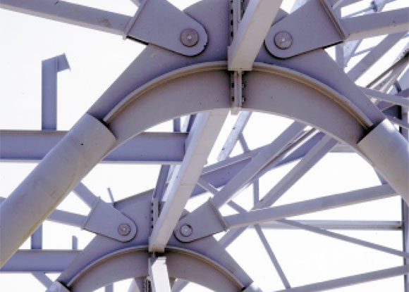
Various structural systems were explored with the arch proving to be the most efficient. The arch followed the natural profile of the plane geometry, ie maximum headroom where the tail fin is and reduced at the wing tips. From a structural point of view an arch is a very efficient structural system acting largely in pure compression minimising bending and deflection. Traditionally the arch reactions are resisted by either using thrust blocks, which would have been large and expensive, or by installing a tie between the arch ends. More usually in a tied arch of this type the tie is placed above the minimum level of the plane increasing the overall height of the building.
To avoid raising the structure, the arch form was extended to ground level through the use of inclined “A” frames in the form of concrete filled tubes. In this way the tie could be placed underground in the form of prestressed reinforced concrete beam. By introducing roller doors in tail fin slots in the gable end of the hangar the elevation could be reduced further. Fit out of accommodation within the hangar envelope can then take place with offices and workshop accommodation located around the support legs, rather than in ‘bolt on’ accommodation at the back or sides of the hangar as is more normally the case.

A key concern in the design was the bending induced in the arch through asymmetric loading. Bending resistance was introduced by forming the arch from a trussed arch 3m deep formed from rectangular hollow section chords and square hollow section lacing. The trusses are spaced 9m and span 90m. Secondary trusses link the trusses together and reduce the buckling length of the chords. Each of the trusses is connected to “A” framed support via a pin. The “A” framed legs are made up of concrete filled circular hollow section legs and a headpiece fabricated from 80mm steel plate. Two wind trusses spanning 90m achieve lateral stability. To gain a detailed understanding of how the structure is behaving it was modelled as a three-dimensional nonlinear model.
By working closely with the steelwork contractor an erection procedure was established which proved both simple, cost effective and reliable. Each 90m truss was split into three segments. A double bay was assembled on the ground comprising two truss segments linked with all connecting secondary trusses and purlins. These segments would then be lifted in place and jointed in the air. After an initial learning curve and some refinements this method proved very successful.

The hangar steel was erected on programme. The hangar construction commenced with ground works in October/November 2001. Steelwork erection started January/February 2002. The main hangar was completed in November/December 2002 with additional office space being added until April 2003. A total of 823t of structural steel (63 kg/m2) and approximately 100t of cold rolled steel was used in this hangar.
This project has been a good example of what can be achieved by close co-operation between the client, the design team and the specialist contractors and how creative design can achieve a result that completely satisfies the client’s aspirations at a cost of no more than conventional solutions and yet lifts the spirits and is a positive addition to our built environment.
Judges’ Comments
A fundamentally simple concept that meets all the taxing demands of a fastmoving industry has generated a clear solution that is elegant in its design, rational in its engineering technology and economic in its means of implementation. This hangar now sets the standards to which others must aspire. TAG’s design and construction team has produced a winner!