SSDA Awards
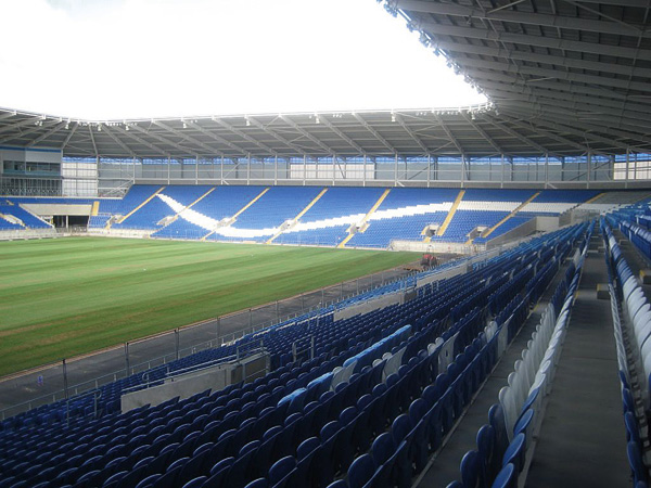
SSDA 2003 – City of Manchester Stadium

Manchester has a new iconic symbol for the city. It was completed in March 2002 as the centrepiece of the hugely successful XVII Commonwealth Games. The stadium was constructed on a derelict site and will act as a catalyst for the redevelopment of the surrounding area.
FACT FILE: City of Manchester Stadium
Structural Engineer: Arup Associates and Arup
Steelwork Contractor: Watson Steel Structures Ltd
Main Contractor: Laing O’Rourke Ltd
Client: Manchester City Council
It is an example of a building whose architecture and structure has not only captured the imagination of those who use it but will bring long term benefits to the residents of both the surrounding area and the city as a whole.
The Stadium structure utilises a mixture of structural systems. In-situ and precast concrete were used to construct the stadium bowl and structural steel supported from a cable-net of masts and steel cables to form the roof.
The City of Manchester Stadium is a remarkable structure due to several key features:
- It is one of the most cost effective quality stadia of its size in Europe. Typical examples of multi-function components of the building are:
- The stadium is circular to provide optimum views for spectators. It sweeps up from low sides on the North and South elevations that allow sun on to the grassed area, to high sides on the East and West giving protection from prevailing winds and low sun angles
- Roof Structural Liner Tray – these 150 deep aluminium panels act structurally to support the roof sheeting as well as creating a hidden zone for acoustic insulation, wiring and roof bracing. The trays also form a visually clean ceiling to the roof that would not usually be economically viable on aesthetic grounds alone
- Concrete Ramp Towers – the eight concrete towers to the east and west of the stadium serve three distinct purposes. Firstly they support the spiral ramps that provide access and egress for spectators. Secondly the spaces within the concrete ramp drums are utilised for plant as well as toilet facilities. Finally they provide an elevated support for eight of the 12 roof masts
- The stadium is unique in Europe as a building of two distinct lives – initially a 41,000 seat athletics stadium and then to be permanently converted into a 48,000 seat football stadium (completion Summer 2003). The construction flexibility is central to the success of this transformation. The primary roof support structure that consists of a pre-stressed mast and cable-net system is independent of the roof-plane rafters and purlins. This allowed the roof to be added below the cable-net in whatever sequence was required
The innovative mast and cable-net roof primary structure utilises a ‘grounded tension ring’ in order to create a prestress field against uplift wind loads. The structure comprises 12 cigar-shaped tubular steel masts up to 65 metres high. Eight of the masts sit on cone shaped tubular supports on top of the spiral concrete ramps at the East and West sides. The masts support 76 spiral strand forestay cables in fan-shaped groups of five or seven cables per mast. Each forestay supports an individual roof rafter. Just above the roof surface all forestay ends are connected by a system of four spiral strand cables that form the grounded tension ring (also referred to as the ‘catenary’). Prestress to the catenary and cable-net is provided by the four corner-ties anchored to the ground. The top of each column is tied back to the ground by pairs of backstays comprising groups of ‘Macalloy’ high tensile steel rods.
The erection scheme provided the greatest challenge for the team. The rafters, masts and pyramid supports were fabricated in transportable sections and then welded on site into complete elements. After carrying out risk assessments on the erection scheme it was decided to construct the rafters on temporary props generally supported on the concrete terrace. This allowed the construction of other elements to proceed at the same time without the constraints of sequence. If the masts and cables had been erected first, to provide support for rafters, any delay to the critical cable assembly would have a corresponding delay to the remaining work.

The catenary cables were assembled at ground level in the bowl of the stadium, on jigs which supported the nodes in the correct geometry. After clamping the four cables at the node points, the complete assembly was lifted on top of the rafters and supported on temporary works.
In conjunction with the above, masts were erected and made stable by the permanent backstays and temporary forestays connected to the temporary props supporting the rafters. At this stage the masts were positioned one degree forward of their pre-set geometry to facilitate fixing the permanent forestay cables.
The corner ties to the completed catenary were erected, connected to the catenary, and a pre-tension of 200KN applied. The permanent forestays from mast to catenary were fixed using a predetermined sequence that ensured the catenary displacements were within acceptable limits.

The final tensioning of the cable net could now commence – the basic sequence being to increase the corner tie tension to 1000KN simultaneously at each corner using temporary hollow jacks on the ends of the cables. This was followed by releasing the temporary forestays whilst at the same time adjusting the permanent backstays to maintain a minimum tension.
When the majority of the load had transferred from the temporary forestays into the catenary the forestays were then released. Once all the forestays were released final tensioning commenced. Firstly all the backstays to the masts were jacked to length, all four pairs simultaneously, and the pins inserted into the anchorages. After all the backstays were complete the final tensioning of the corner ties commenced simultaneously increasing the tension to 2550KN. The final activity was to jack up the rafters from their supports install its linking member to the catenary node and remove the props.
In summary the structural solution for the stadium has produced a design that not only adds significantly to the overall stadium architecture but is one of the best valuefor- money stadia of its size in Europe. It is a demonstration of overall building design, which can be attributed as much to the engineering and construction as to the architect.
Judges’ Comments
The memorable “Mexican wave” roof is suspended from beautifully engineered tension masts, which themselves grow out of the distinctive circular ramp access routes. A catenary ring cable holds the roof down and this is incrementally readjusted to accommodate the fourth side of the stadium now being constructed. Overall the impression is of an integrated and ingenious building where the design and construction of the steel work is central to the entire project.