Projects and Features
A new generation hangar for Farnborough Airport
Farnborough airport, long the home of the famous air shows, is being re-developed as a business airport. TAG Aviation, the new owners, wanted hangars with a better image than the standard box type. But the buildings needed to be economical and to work well. Thomas Gabele reports.
FACT FILE: Farnborough Airport redevelopment
Architect: Reid Architecture
Structural engineer: Buro Happold
Project manager: Bovis Lend Lease
Steelwork contractor: Rowecord Engineering
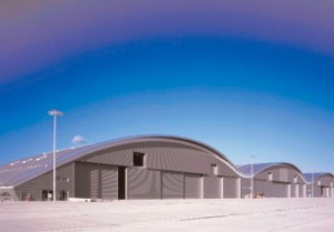
Part of the £45m redevelopment of Farnborough Airport, which also includes a 35m high air traffic control tower and a new terminal, the £9m new hangar is 290m long, 45m deep and 20m high at the apex. The client’s requirement was for a three-bay hangar, with one bay capable of housing two Boeing Business Jet (BBJ) aircraft. The other two bays would be used for a combination of smaller aircraft.
To accommodate two BBJs, the clear span of each bay of the hangar would need to be a minimum of 90m. It was vital for the client to maintain as much flexibility as possible within the hangar to accommodate the wide variety of aircraft that use Farnborough.
The Challenge
TAG Farnborough Airport has a vision for the airport and seeks to lead in this field through the design and quality of the facilities it provides. The challenge set for the design and construction team of Reid Architecture, Buro Happold and Bovis Lend Lease, was to accommodate the functional requirements with a design aesthetic that reflects the qualities of the TAG brand image, yet without a cost premium, over the more conventional design-and-build ‘shoe box’ hangars. It was also important that the design matched the aspirations of the local authority as the Farnborough site lies within a ‘strategic gap’ where visual amenity is a key concern.
The Solution
The first and most important step to finding a solution was to identify the exact client requirements. Particular attention was paid to the way the hangar was to be used during its normal operation. The critical parameters were:
- how the aircraft moved around the hangar
- what maintenance facilities were required
As with most buildings, a very significant component of cost is the cladding – it was essential to reduce the area of the elevations as much as possible. The added benefits of this are improved aesthetic, reduced windload on the structure and reduced impact on the surroundings. In discussion with the client it became evident that the larger planes would only be moved in and out of the hangar, and there was no requirement to turn the aircraft round inside. This was the key to the design. By plotting the space requirements for the planes, it became evident that the eaves could be quite low and the maximum height was required over the tail fins of the planes. The space requirements were governed by three main factors:
- the wing span of the two Boeing Business Jets side by side
- the maximum height at the tail fin
- a requirement to move a collection of smaller aircraft with a maximum tail height of 9m around the hangar
Based on these requirements the following spacial requirements were derived:
- Minimum clearance 78m (2 x BBJs side by side)
- Minimum tail clearance 12m (based on BBJ)
- Minimum tail clearance to most of hangar area 9m (based on tail of Gulfstream aircraft)
Structural Design
By utilising these space requirements Buro Happold explored various structural solutions including the traditional primary and secondary roof girder system. When plotting the actual space requirements around an elevation of a BBJ, and the fact that these large aircraft would be moving only in and out along a straight line, it became apparent that an arch profile would best fit the minimum spacial requirements.
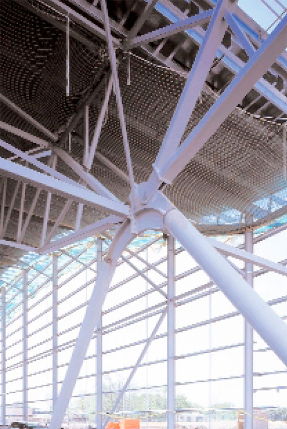
Using the arch as a profile has a significant structural advantage. As a structural system, axial compression is the main force transmitted – bending and deflection are limited. The resultant arch profile was a 90m span with a rise of 12.0m. To achieve the necessary clearance the arches were jacked up 5.5m onto ‘A’ framed legs.
To resist the axial thrust generated at the support points, either thrust blocks or a tie installed between the arch ends are commonly used. Resisting the thrust generated by a 90m arch would require substantial thrust blocks, which would not suit the functionality of the hanger. It was therefore decided to use a tied arch.
If the tie were installed at the arch ends, the whole structure would have to be jacked up by another 6.5m to avoid clashing with the tail fin of a large business aircraft. To avoid this, the inclined “A” frame supports were used to extend the arch down to ground level. In this way, the tie could be located underground in the form of pre-stressed tendons protected from corrosion and damage, by casting into a concrete beam.
To further reduce the building’s elevation in height and the size of the hanger doors, the whole structure was lowered to achieve a 9m clear vertical opening, suitable for most business aircraft. To accommodate the tail fin of the BBJ, “cut outs” which could be closed using roller shutters were introduced into the gable end.
A key concern during the design was snow loading. Since the three hanger bays are joined, a large valley is formed and a significant amount of asymmetric drift loading could cause significant bending in the arch.
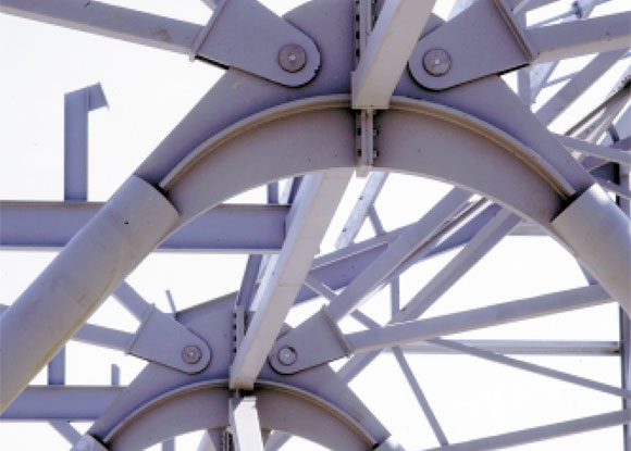
Bending resistance was introduced by forming the arch from a truss 3m deep formed from rectangular hollow section chords and square hollow section lacing. The trusses are spaced 9m and span 90m. To reduce the buckling length of the trusses, a series of secondary trusses link the arches. Each of the trusses is connected to the “A” frame supports via a pin. The “A” frame legs are made up of concrete filed circular hollow section legs and a headpiece fabricated from 80mm steel plate. Wind trusses spanning 90m achieve lateral stability.
To gain a detailed understanding of how the structure is behaving under load in particular wind and snow loading, it was modelled as a three-dimensional, non-linear model.
Construction
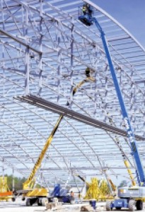
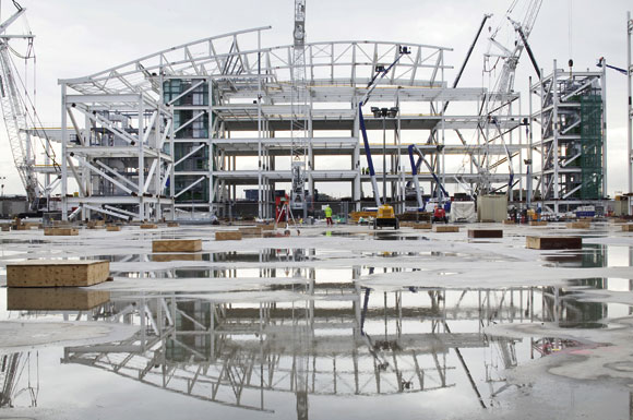
By working closely with the steel fabricator an erection procedure was established which proved both simple, cost effective and reliable. Each 90m truss was split into three segments. Initially, a double bay was assembled on the ground comprising two truss segments linked with all connecting secondary trusses and purlins.
These segments would then be lifted in place and jointed in the air. The first truss took approximately 13hrs to erect. The main difficulty appeared to be to simultaneously line up the two truss ends with the pin holes. Subsequently the method was refined and each truss segment was connected to the support first and propped on trestles.
The secondary trusses and bracing was then installed to link the two segments together. This was then repeated on the opposite side and the makeup piece in the middle was entirely constructed on trestles. The completed segments were then rotated into position and joined by using a mobile crane.
After an initial learning curve and some refinements this method proved very successful and a complete arch set could be erected within five hours.
The hangar construction commenced with ground works in October/November 2001. Steelwork erection started January/February 2002, and the hangar was completed in December 2002. Additional office space will be added until April 2003. A total of 823 tonnes of structural steel (63 kg/m2) and approximately 100 tonnes of cold rolled steel was used in this hangar.
The Result
The team’s effort produced a three bay hanger, each bay with a clear span of 90m and capable of accommodating two Boeing Business Jet aircraft, or a collection of smaller aircraft.
By using arches to form the roof structure, Buro Happold was able to produce a bespoke hanger to fully satisfy the client’s requirements at a cost comparable to a standard “shoe box” hanger. By utilising the arch action, we were able to limit the steel tonnage to approximately 63kg/m².
Another benefit was that the office and workshop accommodation can be located within the hanger space by placing it around the support legs, rather than having to accommodate offices and workshops in pods at the back of the hanger as is more usually the case.
Thomas Gabele BEng (Hons), MIE (Aust) CPEng is an Associate in Buro Happold Bath office.


