Projects and Features
Reaching for the asymptote – what is an optimal design?
Greatly simplifying the complex subject of structural design, one would imagine that an optimally designed element, or structure, would achieve unity factors of 1.0 for all verifications using the minimum amount of material. That may be true if embodied energy is our only concern, and we consider material use as a metric for ‘carbon’. It probably isn’t true if we are concerned with cost, as there are many reasons why a lower cost solution might well use more material to achieve the same, or better, resistance. Organisations such as SCI have been preaching that ‘lowest weight is not lowest cost’ for three decades.
Using some examples from the very topical subject of performance in fire, in this article Graham Couchman of SCI will illustrate how different definitions of optimal could lead to very different solutions. The purpose of the article is to encourage designers, and indeed those who procure and construct buildings, to understand what they want and be open to different approaches.
Introduction
Guidance on how to design for more sustainable construction is due for publication by SCI in early 2024 [1]. Its production acknowledges that for the first time in a generation, designers are now having to consider metrics other than (initial) financial cost when striving for an optimal solution. Having spent a career with the mantra of ‘lowest weight is not lowest cost’ it requires a serious change in mindset. This change of mindset will also require clients to change their approach of choosing the designer proposing the lowest fees, as lowest design fees will rarely lead to the lowest cost solution. The latter point has been well demonstrated by work undertaken at the University of Cambridge in recent years [2], showing how much steel is wasted as a result of reducing design time. Having to consider different definitions of optimum certainly complicates things. Is a ‘great’ design one that costs the least to build, one that costs the least to design (some aspects of which are what we have traditionally got as a result of how contracts are organised), one that uses least material, one that will be adaptable in the future, or reuseable, and so the list goes on. The examples below, both of which relate to design for the fire limit state, illustrate design choices that could be made, and should be informed by the definition of ‘optimal’. One is obvious, the other is more subtle.
Composite slabs – is all that concrete needed?
Composite slabs are designed considering three very different scenarios:
- The ability of the decking to support its self-weight, the wet weight of concrete, the self-weight of any mesh, and construction imposed loads,
- The ability of the composite slab, comprising in-situ concrete with mesh and/or fibres and steel decking acting as external reinforcement, to support normal state loads,
- The ability of the composite slab, with resistance reduced due to elevated temperatures, to support reduced loads at the fire limit state.
For the first two scenarios both resistance and stiffness of the decking and slab respectively must be adequate. Stiffness is not explicitly considered for fire design. In over 80% of cases the first of the scenarios above, the construction stage, governs. This indicative figure is for the UK market, despite our common practice of thru-deck welding of the shear studs, which facilitates making the decking sheets continuous and therefore undergoing significantly reduced deflections compared to simply supported sheets. When the ability of the decking to support construction dead and imposed loads limits the spans that can be achieved, it is clear there is not point in say adding depth to the slab in order to increase the composite resistance. Indeed that would be counterproductive as it would add to the wet weight of concrete. Table 1 distinguishes the spans that can be achieved for each design condition for a typical slab with the attributes below:
- 150 mm total depth (composite stage assumes, as is almost universally done in the UK, that the slab is discontinuous at both ends despite the physical reality)
- 60 mm trapezoidal decking, 0.9 mm gauge (assumed continuous at one end)
- REI 60 minutes (concrete assumed to be continuous at both ends)

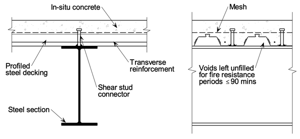
However, it is worth considering why the design of an element such as a composite slab is so often governed by the construction stage. Developments in decking profiles over the past 25 years have been driven by a desire to reduce the volume, and therefore wet weight, of concrete. The difference in the volume of the voids formed in a slab with either nominal 50 mm re-entrant decking or nominal 60 mm trapezoidal decking is immediately clear when the decking geometries are considered (Figure 1). However, to achieve adequate performance in fire requires a certain depth of concrete. Requirements for acoustic attenuation may also dictate the depth (mass) of the slab. In fire the depth is needed to ensure that the unexposed upper surface of a slab with a fire below stays below a certain temperature (to satisfy the insulation criterion in Approved Document B[3]). In some situations, such as short spans with low imposed loads at the final stage, a more optimal solution might use less concrete, and other means of assuring fire and acoustic performance. Depending on what metric defines optimal, this could be through the provision of extra layers rather than just increasing the thickness of concrete. So the real condition governing design in numerous cases is actually fire, but this is not transparent as it manifests itself in software etc as a ‘minimum’ acceptable slab depth that then impacts construction stage design.
Composite beams – what performance is important?
When considering the fire protection of a composite beam, the cross-section is typically broken down into elements. BS EN 1994-1-2 Clause 4.3.4.2[4] gives rules for un-encased downstand beams and notes how the section should be divided into parts (flanges, web, slab), assuming no heat transfer between them (Figure 2). Various sub clauses identify how to calculate the increase in temperature of a given part, as a function of time. Having established the temperature of each part for the required time period (the temperature varies, amongst other things, with the ratio of surface area to volume of the part), the amount of fire protection can then be determined. Clause 4.3.4.2.2 (9) considers the issue of transverse decking laid on the beam, and recognises that when voids thus form above the steel beam top flange, only part of which is then in direct contact with the slab, their ‘size’ can affect the flange temperature. The code assumes that more than 85% direct contact between beam and slab is as good as total contact, providing protection to the upper surface of the flange, whereas less than 85% leaves the flange ‘exposed’ (unless the voids are filled with appropriate material). Software from proprietary beam manufacturers recognises this, and uses an approach whereby temperatures in the top flange are ‘adjusted’ to allow for more than 15% voids. These higher temperatures must be addressed by using increased fire protection.
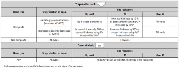
Table 2 is reproduced from SCI’s recently updated publication P300[5] and presents simplified rules for achieving the required level of fire protection when voids are unfilled, for different fire resistance periods. It shows that for 90 minutes a considerable increase in protection may be required. This could have significant and not obvious consequences on cost/programme if it resulted in a need for an additional coat of offsite intumescent, because of the requirements for drying time.
However, as noted the procedure described above is based on considering each part of the composite cross-section in isolation, and ignores the fact that some parts are more important than others. The upper steel flange of a composite beam is rarely important, post-construction stage, because the concrete slab carries most if not all of the compression. This is why composite beams often have asymmetric steel flanges. Moreover, when there are large web openings the design of the beam is likely to be governed by web-post buckling, not compression flange (steel and/or concrete) resistance. So why waste fire protection material to ensure a level of performance of a cross-section part that is not needed? The answer is ease of design, sometimes combined with a lack of understanding.
When sufficient fire protection is used, it ensures that ambient temperature design will govern, so elevated temperature structural design is not explicitly needed. This is achieved when the reduction in resistance with temperature is less than the reduction in load factors when fire is considered. However, even without explicit design at elevated temperatures, it might be possible to produce a more efficient design for the scenario described above. The presence of higher temperatures in the upper steel flange, sufficiently high for fire design to govern, could be modelled in an ambient design by using a smaller upper flange, rather than reduced material strength, to represent a loss in resistance. If this smaller beam still worked then the higher temperatures at the fire limit state would not be a problem, and some of the fire protection could be ‘saved’ to provide a more optimal design. This conclusion is based on the assumption that any reduction in shear connection resistance with temperature would not be relevant This assumption is not unreasonable given the reduction factors for studs and associated concrete given in BS EN 1994-1-2 Cause 4.3.4.2.5.
Conclusions
The design, construction, use and ultimately removal of a building at end of life are each in themselves complicated, and taken together that complexity increases due to the interactions between these different phases. It then becomes extremely difficult to identify what is an optimal design. Traditionally optimisation has considered the simple metrics of design fees, and more significantly construction cost. More recently whole life (financial) cost, and ‘carbon cost’, have come into consideration. This is therefore an interesting time for designers, who will be able to use their skills and experience to come up with solutions that are more broadly optimal.
References
- Design recommendations for sustainable steel construction (P449), The Steel Construction Institute (to be published)
- Moynihan M. C. and Allwood J. M. Utilization of structural steel in buildings. Proceedings of the Royal Society. August 2014
- Approved Document B: Fire safety. The Building Regulations 2010. UK Government, 2022
- BS EN 1994-1-2:2005 Eurocode 4. Design of composite steel and concrete structures. General rules. Structural fire design. BSI
- Composite Slabs and Beams using Steel Decking: Good Practice for Design and Construction (P300, Third Edition), The Steel Construction Institute. 2023


