Projects and Features
Protected portal frames on fire boundary
Where single storey buildings have external walls close to a site boundary, the walls are required to have fire resistance. Such external walls have commonly in the past been provided with moment-resisting bases and fire protected columns. Richard Henderson of the SCI discusses an alternative approach to providing moment-resisting bases that has been adopted more recently.
Introduction
Building Regulations1 require that external walls of single storey buildings that are close to site boundaries have fire resistance to protect the next-door land or property. Any structure that provides support to such walls must also have fire resistance. Portal frame structures with walls close to a site boundary have commonly been constructed with moment-resisting bases and fire protected columns to provide the necessary protection. SCI’s guidance document P3132 assists designers in satisfying the Building Regulations and is referred to in them. The publication provides guidance on the design of the moment resisting bases by providing methods of calculating the forces on protected columns that develop due to the effect of a fire on unprotected rafters.
Recently, as a result of changes in the relative costs of various forms of construction and fire protection, there has been a move away from providing moment resisting bases to columns on fire boundaries. The equivalent result is achieved by constructing standard bases to the columns and providing the entire portal frame span next to the fire boundary (referred to here as the boundary span) with fire protection. The structure is therefore able to provide support to the external wall for the required period and satisfy the Building Regulations.
Portal frames with several spans
Where this strategy is adopted in portal frames that have several spans, the boundary span is fire protected and the adjacent span is unprotected and subject to heating in the event of a fire. As set out in P313, the rafters of the unprotected portal frame weaken and form plastic hinges with less than 10% of the normal plastic moment resistance. This behaviour leads to the rafters inverting and results in horizontal and vertical loads being applied to the supporting structure, in this case, the protected boundary span. The arrangement of the structure is such that the method of calculating the loads from the unprotected rafters described in P313 can be applied and the protected boundary span checked to ensure the structure stands for the required period. According to P313 section 3.14, the loads applied by the unprotected rafters can be based on a symmetrical frame, even though one of the columns may be unprotected
Hit and miss fames
Hit and miss portal frames are so-called because internal columns on valley lines are omitted in alternate frames to provide more flexible internal space. Buildings may also be constructed with internal columns omitted in two adjacent frames in a hit, miss, miss, hit arrangement. Loads from the miss frames are supported on valley beams and transferred to the hit frame valley columns.
The absence of a valley column means that miss frames are less stiff in-plane than hit frames and bracing in the plane of the roof is often provided on the valley lines to share loads between the frames. In the fire load case, it is likely that bracing will be required to transfer loads from the miss frame(s) to the hit frames, unless the valley beam is designed for bending in two directions.
Behaviour in a fire
P313 describes the behaviour of portal frame structures in real fires and makes suggestions for the fire protection of various elements when designing boundary columns with moment-resisting bases. This guidance can be applied to structures where fire protected boundary spans are substituted.
Valley columns were observed to have remained standing following seven out of eight severe fires. As a result, P313 recommends that fire protection to valley columns can be omitted unless the ratio L/Y < 1.6 where L is the span of the portal frame and Y is the vertical height of the frame to the end of the haunch on the rafter centreline. If the frame formed by the protected outer column and protected rafters is not strong enough to resist the applied horizontal force, fire protection can be applied to the valley column to form a complete portal frame to provide the resistance. In most cases the valley column will need protection.
P313 also indicates that valley beams are assumed to be lightly loaded in a fire and do not require fire protection. With modern cladding and the increased placement of photovoltaic panels on roofs it is no longer considered reasonable to assume valley beams are lightly loaded and do not require fire protection. Table 2.1 in P313 indicates cladding arrangements where it is assumed that the full weight of the outer covering remains in place at the time of rafter collapse. It is reasonable to assume that external photovoltaic panels will also remain and the panel weight should be allowed for when checking the resistance of the frame.
Out of plane stability
The possible modes of collapse in the direction perpendicular to the span of the portal frames must be considered. In the case of boundary columns supported on moment resisting bases described in P313, the out of plane (longitudinal) stability of each perimeter column is assumed to be provided by its base fixity. The lateral restraints provided by the longitudinal members chosen for the permanent works are considered to be adequate without fire protection according to P313 section 2.8.
Stability of the structure in normal conditions in the longitudinal direction can be achieved in different ways: by providing discrete stability systems in the perimeter walls and in the valley lines, or providing wall bracing in the perimeter walls and roof bracing spanning from exterior wall to exterior wall. Stability systems on the valley lines are likely to be goal-post frames to avoid restricting the floor space, particularly in hit and miss framed buildings.
If no moment resisting bases are to be provided, out of plane stability must be provided by alternative means. The permanent vertical bracing and longitudinal eaves beam should be fire protected to ensure stability for the fire resistance period.
Where longitudinal stability to valley lines is provided by a plan roof truss spanning from one outside wall to the other, the members in the plan truss should be fire protected in the boundary span. In the most extreme case, the whole valley line nearest to the boundary wall could collapse completely in the longitudinal direction, although the description in P313 suggests this is unlikely. Such a collapse will involve a rotation of the boundary span in plan. The provision of a fire protected plan truss in the boundary span together with protected valley beams and valley columns will inhibit complete longitudinal collapse of the frames on the valley line. If some longitudinal movement of the valley line occurs, the proportions of the frame limit the reduction in height of the boundary wall, maintaining the integrity of the boundary.
Where longitudinal stability systems (bracing or goal-post frames) are provided on the valley lines, fire protection to these systems (including longitudinal members between frames) should be provided on the valley line of the boundary span.
Recommended treatment of a boundary portal span
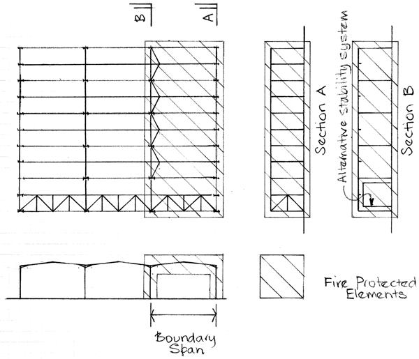
The elements that require fire protection in a particular arrangement of building will vary depending on the structural arrangement (conventional, hit-miss etc.), geometry (span, column height etc.) and the loading present. An appropriate analysis should be carried out case by case to identify those parts of the boundary spans that are required to resist the loads they will be subjected to.
Where a protected boundary portal span is to be adopted, fire protecting many of the following elements will be necessary, noting that the plan bracing and valley line longitudinal stability systems are alternatives.
- boundary span perimeter columns;
- boundary span rafters;
- boundary longitudinal stability system;
- boundary longitudinal eaves member;
- boundary span plan bracing;
- boundary span valley columns;
- boundary span valley beam;
- boundary span miss frame bracing;
- boundary span valley line longitudinal stability system.
These elements are shown diagrammatically in Figure 1.
Conclusion
Protection to a fire boundary equivalent to that described in P313 can be achieved by fire protecting elements in the portal frame next to the fire boundary (the boundary span) as described. The protected boundary span should be checked to demonstrate adequate resistance to the forces from the collapsing rafters in the next span determined as described in P313.
References
- Approved Document B Volume 2,
Buildings other than dwellings - Simms, W I, Newman G M,
Single storey steel framed buildings in fire boundary conditions,
SCI P313, 2002.


