Projects and Features
Hybrid modular systems using a steel-framed podium
Mark Lawson of the SCI discusses some of the recent research and developments in modular construction.
Modular construction has established itself in the UK for medium and high-rise residential buildings, such as student residences and hotels, in which there is often need to provide open plan space at the ground floor level and for basement car parking. The structural system generally adopted is to support the modules on a steel-framed podium or transfer structure in which the beams align with the load-bearing walls of the modules and columns are placed at multiples of the module width. This article reviews some of the design considerations in planning modular buildings when supported by a steel framework and is based on the results of a recent research project called MODCONS, which was carried out with support from the European Commission.
Modules supported by a steel-framed podium
The modules are relatively lightweight and so the steel structure can be designed to support the vertical loads from the modules. For modular buildings of six to eight storeys, long span cellular beams may be used to provide open plan space below, as shown in Figure 1. The columns are placed at 7.5m spacing which means that the modules are 3.7m wide allowing for a gap between the modules. This is the optimum solution for both the modular system and the open plan space below.
Figure 1: Support to modules by steel-framed podium structure
For taller buildings, it is efficient to ‘cluster’ the modules around a braced steel or concrete core, which provides the overall stability of the building. In this building form, the modules transfer vertical loads. A configuration of modules using this principle is illustrated in Figure 2 in which 8 apartments comprising 16 modules are placed around the core. Access to each apartment is provided from the central core.
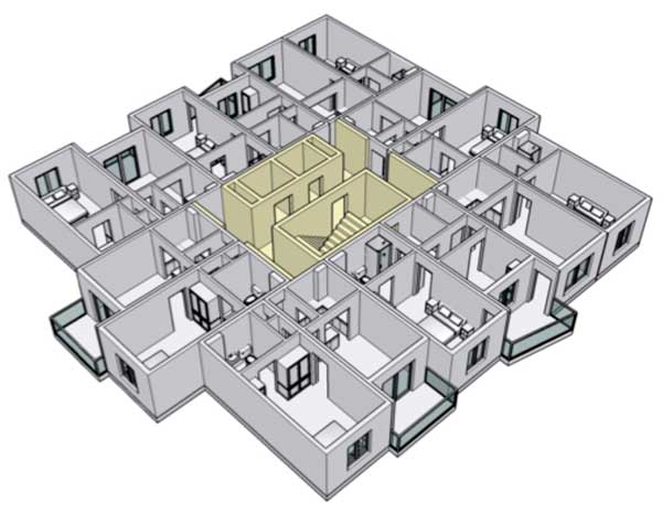
Figure 2: Typical layout of modules in high-rise buildings
(courtesy HTA Design)
Analyses of modular systems on a steel-framed podium
In the recently completed European Commission Framework 7 project called MODCONS, the Steel Construction Institute worked with modular manufacturer, Futureform and partners from Spain, Portugal and Finland. The behaviour of these hybrid structural systems were analysed when subject to various actions including seismic effects and loss of supports to take account of potential robustness (avoidance of disproportionate collapse) scenarios. The cases considered used two lines of modules with a braced corridor between the modules. Studies were made of four-storey and six-storey high groups of modules supported on a floor grid of 7.5m square and 8.8m × 7.5m including the corridor and also a 16.3m × 7.5m long span grid. The objective was to evaluate the deflections of the hybrid system for various actions, and the forces in the supporting frame and in the connections between the modules. An example of these analyses is shown in Figure 3.

Figure 3: Analyses of structural frame supporting 4 levels of modules above. (a) Deflection (exaggerated) of steel frame supporting modules
(b) Deflection when internal column is removed to simulate robustness
Planning guidelines
The following information may be useful in planning a modular project supported by a steel-framed structure:
- A typical light steel module weighs 3 to 3.5 kN/m² floor area, or 10 Tonnes for a module of 30m² floor area. The weight will be higher if the modules are supplied with a concrete floor instead of a light steel joisted floor.
- The module sizes are limited mainly by transportation, an external width of 4.2m can be transported without escort. Module lengths may include the corridor.
- Constraints of local roads and permitted times of working should be agreed at the planning stage as they will influence the optimum design solution.
- For internal planning purposes in residential buildings, an internal module width of 3.3m to 3.9m is efficient. Openings in the side walls of modules can be introduced, depending on the loads that are transferred.
- A combined wall width of 300mm and a combined floor and ceiling depth of 450mm should be allowed for in the planning of modular systems although these dimensions may reduce for some modular systems.
- A rigid welded frame often using RHS sections can be introduced at the ends of the modules if a fully glazed façade or large patio doors are required. These RHS members can also be used to provide support to balconies.
- Installation rates of 6 to 8 modules per day may be used in planning, although times of working, bad weather and winter working will influence this rate.
- Beams at the transfer level should support a composite floor slab (also needed for diaphragm action) and should align with the load bearing walls of the modules.
- A characteristic line load of 15 kN/m per module wall and per storey may be used for scheme design to determine the loads acting on the beams at the podium level.
- Columns should be placed at typically twice the module width along the building façade. A spacing of 7.5m to 8.0m would provide for 3 car park spaces below.
- Beam spans equal to the room length plus the corridor width will usually be most efficient (typically 7.5m to 10m span).
- The modules will also act to stiffen the beams and so the actual deflection response will be 20% to 30% less than for the beams acting alone. The deflection of the beams under the weight of the modules and imposed loads should be limited to span/360 but not exceeding 30mm to avoid damage to the finishes to the modules.
- The vertical services within the modules are often distributed horizontally at the podium level through web openings in the beams. A separate service zone may be required above the podium level in cases of mixed tenure, such as housing above a supermarket.
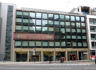
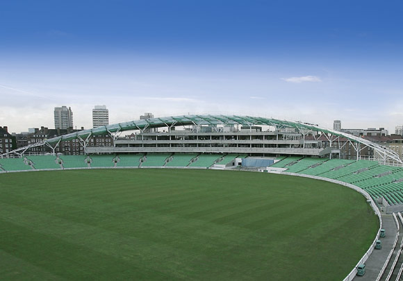
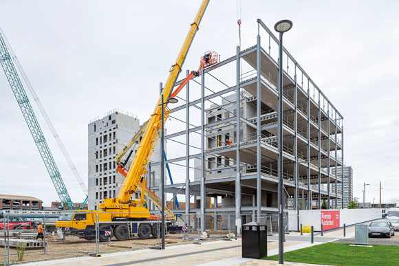
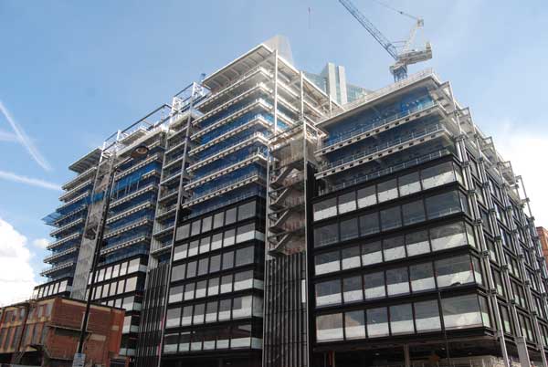
Figure 4: Completed modular hotel on Lavington Street, Southwark showing the use of a first floor steel podium structure
Case example
A good example of this form of construction is a hotel near the busy Southwark Street on London’s south bank which consists of 192 rooms and corridors integrated within the Futureform modules of 15m length. The completed hotel is shown in Figure 4. The modules are supported by a single storey steel frame with the hotel reception and restaurant at ground floor.
A fully glazed façade wall was created by a welded frame using 80 x 40 RHS sections. This rigid frame provides resistance to horizontal loads acting on the five-storey assembly of modules, and also provides the attachment points between the modules. Modules were lifted into place at an average rate of 6 per day by a 500T mobile crane with a long boom positioned on the roadside at Lavington Street. The installation of the modules took only 5 weeks out of a nine-month construction programme, saving an estimated 6 months relative to more traditional concrete-framed construction. This led to estimated savings of 1% of the construction cost per month for the hotel operator.
From a sustainability view point the impact of the construction operation on noise and local traffic was much reduced as modules were delivered ‘just in time’ for lifting directly from the lorry into position. The number of workers on site was reduced to one third of those required in more traditional concrete frame construction. SCI also carried out an embodied carbon study of the modular system and found it had 20% less embodied carbon than a concrete frame with blockwork infill walls.
Acknowledgements
The information presented in this article is only a small part of the work undertaken during the MODCONS project. The project was funded under the European Commission Framework Programme 7 (FP7) for support to SMEs and was coordinated by SCI. The other partners in the project were Futureform Ltd, HTA Design (both UK), Tecnalia, AST and IA3 (all Spain), University of Coimbra and Cool Haven (Portugal), NEAPO and Technical University of Tampere (Finland). Further information about the project is provided at www.modcons-research.eu.