
Projects and Features
Fast delivery for landmark offices

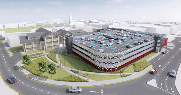
Birmingham’s Snow Hill district is being transformed by new high rise office developments
Steel framed construction has allowed a 17-storey Birmingham office block, complete with a feature glazed atrium roof and bow-string trusses, to be built in just 30 weeks. Ruby Kitching reports.
FACT FILESnowhill Building Two, Birmingham
Main client: Hines
Architect: Weedon Partnership
Main contractor: Balfour Beatty Construction
Structural engineer: Curtins Consulting
Steelwork contractor: Caunton Engineering
Steel tonnage: 2,000t
An increase in demand for high-spec offices in Birmingham is making Number 2 Snowhill a highly sought after property, even though it will not be completed until next year. The 17-storey office block with four additional basement levels for car parking, scenic lifts and a feature steel framed glazed atrium is the second of three landmark office blocks in the Snow Hill area of Birmingham and will be 65m tall.
While this premium office space is eagerly anticipated in the city, construction came to a standstill two years ago, but restarted in May 2011 with developer Hines at the helm and design and build contractor Balfour Beatty keen to pick up the pace of construction.

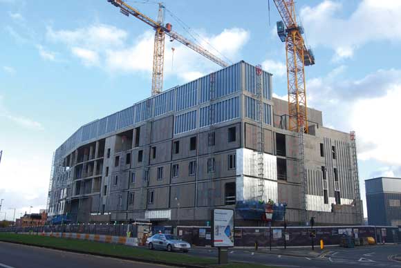
Steel construction has provided the necessary speed of programme
Inheriting a structure added certain risks, admits Balfour Beatty Project Director David Tighe, but careful surveying, checking and rechecking has meant that the new structure has flown up – and to tight geometrical tolerances.
“Every steel connection to the core is bespoke, requiring us to measure the exact geometry and then fabricating elements to exact dimensions,” says Mr Tighe.
The contract was let on a design and build basis to steelwork contractor Caunton Engineering. The company has designed, fabricated and erected over 2,000t of structural steelwork together with metal decking and shear studs for the project.
The building footprint covers an area 54m long by 45m wide and is made up of a 9m by 9m structural grid. The main entrance façade tapers out from ground level up to level 13 where the building then steps back, creating balconies.

Cellular beams create the long span interiors
Double height spaces at level 15 and 16 contain plant. Above ground level, floors are of composite construction with steel beams and columns framing into the three main stability elements – the reinforced concrete cores.
A steel framed solution was an obvious choice for the building explains Yvonne Aust, Curtins Consulting Project Engineer, since it could connect back to the existing cores and construction could proceed quickly. With offices occupying the majority of the floors, clear spans and a flexible structure were also very important for the client.
“Cellular steel beams offered the most practical solution by being able to achieve long spans efficiently without being too heavy,” says Ms Aust. Services could also be threaded through the openings in the beams and concealed within the ceiling void. Metal decking and a 150mm thick concrete slab make up the floor depth.
An atrium occupies the centre of the building from ground floor. The curved roof for this structure is supported by a system of steel “trees” which spring from levels 14 and 15. The tallest double-storey tree sits at level 14 and is made from a 406mm diameter circular hollow section “trunk” with four “branches” supporting steel beams in the atrium roof. The remaining “trees” sit at level 15 and support the perimeter of the roof. These elements are all circular hollow sections, apart from twin box section columns which support the lower edge of the roof and sit at level 14.

Snowhill’s feature atrium takes shape
“Caunton erected the atrium roof in its factory first to make sure everything would fit perfectly because there was no room for error on site,” says Mr Tighe. He adds that there is sometimes just a few days between a survey being carried out, steel elements being approved and then fabricated. The atrium steelwork has been erected using tower cranes at night time, when there is less demand for cranes by other trades. Some floorplates around the atrium have been left out to allow some of the longer roof elements to be slewed up through the building.
Bow-string trusses which support glazing for the scenic lift offer some of the most technical challenges for the design and build team on this project. The trusses were originally designed to work in tension, but the main contractor felt that this would take too long to build and impact on the construction programme. “Building the bowstring trusses in tension meant that we’d have to weigh them down from the top so the trusses could only be erected after the [entire] main structure had been built,” recalls Mr Tighe.
A fair amount of teamwork was required when it came to the design of the trusses. To allow them to be erected as the building went up Curtins and Caunton had to redesign them so that some tension elements resisted compression. Caunton Steelwork Designer Matt Shimwell explains how the bow-string trusses work: “To maintain a very slender design, combinations of triangulated compression and tension members were used. These members took the form of tapered Macalloy compression struts and tension rods. The glazing is supported laterally at each storey level by means of both feature bow-string trusses and cantilevered arms braced off the shear walls. To enable the structure to be erected from the ground up, tapering vertical trusses act as columns which support approximately 35t of glazing. The glazed panels also transmit an eccentric load to the bow-string trusses, which is resolved into tension forces resisted by inner vertical tie rods.”
The project is due to complete in January 2013.

Flush steel to concrete connections create Snowhill’s atrium
Steel beam connections to concrete cores
In multi-storey buildings where stability of the steel frame is provided by reinforced concrete cores, steel beam to concrete core connections are required. Considerations that influence the design of these types of connections include:
• buildability and safety
• construction tolerances and dimensional variations
• deflections and long term movements
• load transfer between components
• variability in materials
• durability and maintenance
• fire protection
• cost (both of the connection and of installation)
• design responsibilities and design programming.
Two important aspects of connection design include load transfer and construction tolerances.
Load transfer at the connection between the steel beam and the concrete core requires the following to be considered:
• the effects of concentrated load on supporting elements
• the effects of eccentricities on the supported and the supporting elements
• the ability of reinforcement in the concrete wall to provide adequate tying action (for robustness requirements)
• the ability of the connection to accommodate building movements and tolerances.
Dimensional variations associated with in-situ concrete elements, are normally significantly greater than those associated with steel construction, hence the expected dimensional variations must be reflected in the amount of adjustment that is provided at the connection detail.
Construction tolerances are the permitted variations from nominal dimensions. These tolerances are taken up by slotted holes, shims or other devices. Brackets designed to accommodate particularly large tolerances can be problematic, in that they sometimes result in high levels of eccentricity at the point of load transfer from one element to another. The benefit of allowing high levels of adjustment to accommodate the maximum dimensional variation must therefore be balanced against possible increases in the size, cost and complexity of brackets, arising from increased eccentricities.
Connections between steel beams and concrete core walls can be subdivided into those with or without pockets, where pockets are openings cast into the concrete wall using specially designed box-outs in the formwork.
For the pocket type connection, a steel beam is introduced into the opening and is located using shims bedded on epoxy or grout. The beam is attached to the reinforcement in the wall to form a temporary connection, and the opening is in-filled with well compacted concrete. Shear studs or drag cleats can be welded to the steel beam during fabrication to enhance the anchorage into the concrete. This detail provides a simple connection that permits high levels of adjustment. Where large axial forces are to be transferred to the core by the beams, additional shear connectors may be required.
For the connection without pockets, a steel connection plate is cast into a concrete wall so that its surface is flush with the face of the concrete. The plate is pre-fabricated to include welded shear connectors and blind bolt fixings. Stiffened cleats are bolted to the connection plate to provide main beam support, and restrain the top flange. This detail provides a reasonable degree of adjustment and safe temporary location of the steel beam, however, the connection plate is relatively heavy. However, this detail can be easier to construct than alternative details based upon openings in the wall, as it does not require subsequent infilling.
Further information is presented in SCI publication P102 “Connections between steel and other materials”.
 Steel to concrete wall connection with pocket
 Steel to concrete wall connection flush with wall


One thought on “Fast delivery for landmark offices”
Comments are closed.