SSDA Awards
MERIT: Cody Dock Bridge, London
Complex and unique engineering challenges were overcome to design and install a new rolling steel bridge, spanning the entrance to a reinvigorated dock near the mouth of east London’s River Lea.
FACT FILE
Architect: Thomas Randall-Page
Structural engineer: Price & Myers
Main contractor: Gasworks Dock Partnership
Client: Gasworks Dock Partnership
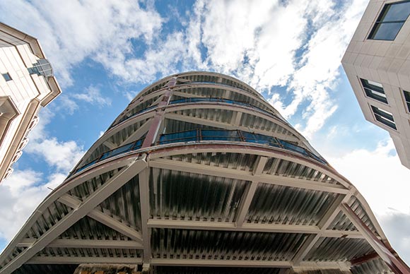
Cody Dock in east London has been brought back to life following many years of restoration and regeneration. Part of the overall scheme is a new steel rolling bridge, that allows vessels in and out of the dock.
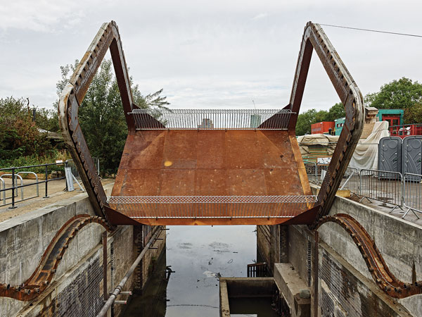
The bridge is carefully counterweighted so that the centre of gravity is level, allowing the 13t structure to roll using only a hand cranked winch. Despite the simplicity of this movement, whereby the deck actually turns upside down, the design process and fabrication revealed complex and unique engineering challenges.
The footbridge is a simply supported structure with a monocoque steel deck spanning 7m over the dock mouth and tapering in depth from 400mm to 550mm at midspan.
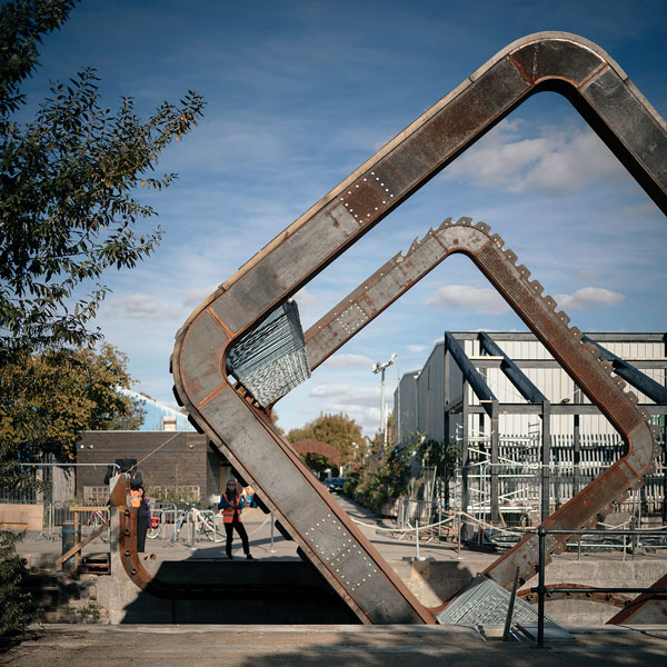
Two 5.5m rounded square portals at each end allow it to roll along undulating concrete abutments, which are cast into the existing masonry walls. The upper section of each portal is counterweighted so that the centre of gravity is raised to the midpoint of the frame.
The path geometry ensures this point remains horizontal when in motion, so that the bridge weight is never lifted vertically. The bridge is driven with a cable by a pair of manually operated winches on one bank, creating a safe, human-powered mode of operation. The handrails are constructed from a welded lattice of steel reinforcement bars and can fold down, via a torsional spring mechanism, for additional clearance height when the bridge is inverted.
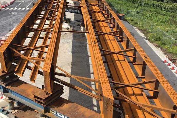
Most of the structure is weathering steel, which has the desired strength, durability, and fabrication accuracy balanced with minimal maintenance requirements. Oak bearing strips fixed to the hoops roll on the undulating steel track, while precision cut weathering steel teeth interlock with Hardox steel pins.
The geometry of the bridge track is said to be loosely based on the square-wheel bicycle problem. Mathematicians Robison (1960) and Wagon (1990) previously derived the path geometry that results from rolling various shapes along a horizontal trajectory.
While the path geometry of a square has been demonstrated to be a set of inverted catenaries, a new solution had to be generated to derive the path of the bridge portals. This involved numerically integrating elliptic integrals to calculate the path shape around the rounded corners (as no analytical solution exists) and combining this result in software with that of a square wheel. This gave a set of transformations that guide the movement from start to finish. In combination with conclusions taken from testing physical scale models, these generated the geometry of the teeth and track.
Monitoring the weight and geometry of the bridge was also vital, in both design and construction. Any increase or offset in weight has the knock-on effect of increasing frictional forces, which determine pin sizes, cable tensions and ultimately the overall deck structure. These constraints lead to an inherently efficient steel structure.
The judges say this intriguing project was realised thanks to a dedicated team working closely together and applying painstaking analysis with “real time” adjustments as the bridge was being fabricated. This ensured a smooth operation on site with the tight tolerances required of a machine.