Projects and Features
City icon showcases steel
 With its unique shape and complex steel design, the Leadenhall Building is set to become a City of London landmark, reports Martin Cooper.
FACT FILE Leadenhall Building, LondonMain Client: British Land
Architect: Rogers Stirk Harbour + Partners
Main contractor: Laing O’Rourke
Structural engineer: Arup
Steelwork contractor: Severfield-Watson Structures
Steel tonnage: 18,000t
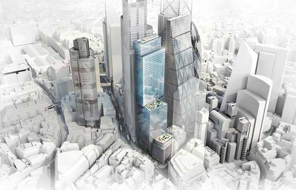
When it comes to tall iconic buildings the City of London and its environs may well have more than any other European capital. The ‘square mile’ has been evolving radically over the last few decades and plans are afoot for even more grandiose structures to enhance its skyline.
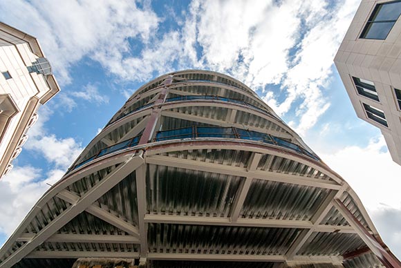
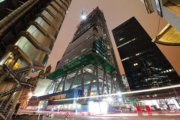
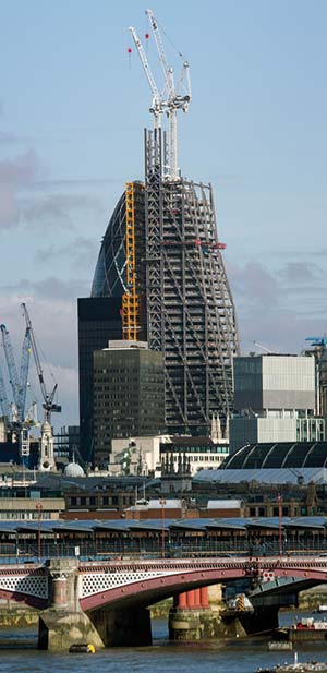
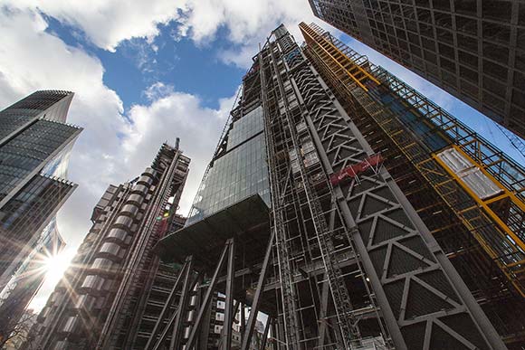
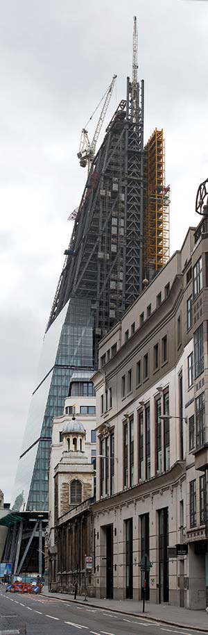
One of the most challenging structures to be undertaken so far is the Leadenhall Building, also known as the ‘Cheesegrater’.
The 225m tall building will provide 56,000m² of prime office space over 42 floors, housed in a tapering, perimeter braced diagrid structure.
“The project is uniquely complex,” comments Andy Butler, Laing O’Rourke Project Director. “Architecturally the structural steel frame is exposed, and because of the building’s shape there are extremely tight tolerances to overcome.”
 Its distinctive triangular wedge shape was developed by architect Rogers Stirk Harbour + Partners in response to concerns about the position of the tower behind St Paul’s Cathedral when viewed from Fleet Street.
As well as having a unique structural shape, the building features provision for highly flexible and open plan office space, and a steelwork design that incorporates architectural detailing of the highest quality.
Maximising the large 16m × 10.5m column grid, all of the lifts, stairs and toilets are housed in an adjoining north core structure (see box over page) that is connected to the offices by a relatively narrow linking section of floor.
For the offices this creates long span flexible spaces, as only six internal columns are needed on the largest lower levels.
Because of the building’s shape each floor is 750mm narrower than the one below, and the typical build up within each 4m storey consists of a 150mm deep concrete slab over 700mm deep fabricated beams. For efficiency, the 2.75mm high structural void of the building is formed from cellular beams with openings to accept services.
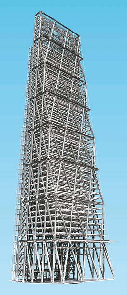
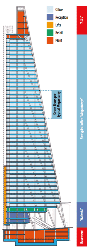 The building’s triangulated geometry is formed by what is known as the mega frame. This expressed steelwork is positioned outside of the structure’s cladding and is divided into eight mega levels. These are 28m high and each contains seven floors, with the exception of the first, which has five floors.
The middle six mega levels contain office floors, while the uppermost accommodates a four-storey plant and generator zone called the ‘attic’.
The building’s ground floor is known as the Galleria, a largely open and landscaped space which will be open to the public. Two hanging banks of escalators within the Galleria will connect Leadenhall Street to the building’s main entrances and lift lobbies at the first and second floor levels.
The third and fourth floor levels are suspended within the space of the Galleria, below the level 5 structure, which is the first level that occupies the building’s full floor plate.
Level 5 also projects through the south side of the building to become a 10m cantilevering wind canopy over Leadenhall Street.
“The Galleria will create a new public space for the City and was a driver for designing and choosing the mega frame,” explains Damian Eley, Arup Associate Director.
The mega frame allows the structure to have a large open ground floor, but to compensate for the lack of lateral support the steel columns have been stiffened in this area.
“The columns landing at ground floor are twin webbed which has been done very subtly as they’re architectural feature elements,” says Mr Eley. “The webs taper outwards in the middle of the section and then back to accommodate the bolted connection,”
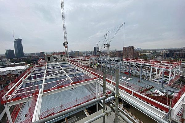
All of the steelwork erection has been completed via the project’s four tower cranes, with the exception of the 23m high Galleria columns which had to be installed by a mobile crane.
Design wise the greatest challenge for the team was how to connect the steel members in a practical way that also worked aesthetically, as all the steelwork will remain in full view.
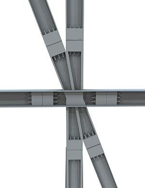
Typically, six elements come together at each joint in a variety of angles within the mega frame, and the connections transfer forces of up to 6,000t in at least three different directions simultaneously.
The solution was to design large 16-20t nodes (see box below), typically measuring 6m × 3m, which connect straight mega frame members via pre-stressed bolted connections. The nodes provide the geometrically complex transitions between the different elements through welded joints between carefully orientated plates.
The Leadenhall Building’s stability is derived from the perimeter megaframe
Stability for the mega frame presented another structural challenge. Because the seven storey mega frame modules are so big the columns require a secondary stability system. This has taken the form of chevron or K-bracing panels, located in the northernmost bays of the east and west faces, the end bays of the north faces and around the smaller fire fighting cores which are positioned in the office zones.
The steel erection programme also encountered a stability challenge. With no central core to provide the steel frame with support during the construction phase, a steel braced core (called the ‘strong box’) was erected in the middle of the frame. This had to resist not only wind loads but the huge loads from the tower cranes.
This temporary structure allowed the steelwork to be constructed around it, and provided stability before each level was self-supporting via the external mega frame columns. The temporary works extend to a height of 14 levels and were dismantled and reused several times during the construction programme.
Because of the building’s shape it has an inherent tendency to lean towards the north by as much as 160mm at the top.
This has been corrected during the erection by a process dubbed ‘active alignment’ in which the diagonal mega frame members on two elevations are subsequently shortened so as to bring the building back into its correct position.
The readjusting of the structure is done three mega levels below the erectors and involves the removal of sacrificial shims that were added during the erection process.
The Leadenhall Building is currently on schedule to meet its May 2014 completion date.
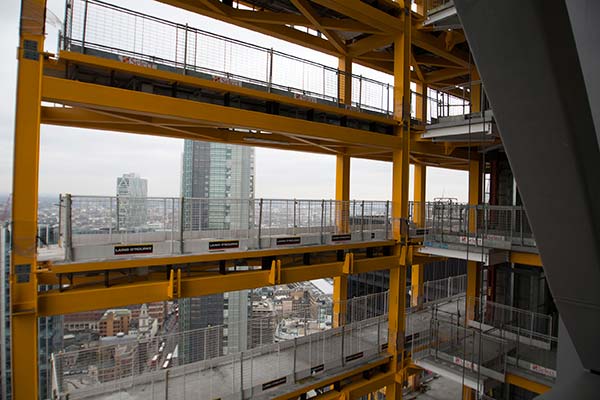
The yellow steelwork north core houses the lifts and service risers
Prefabricated nodes
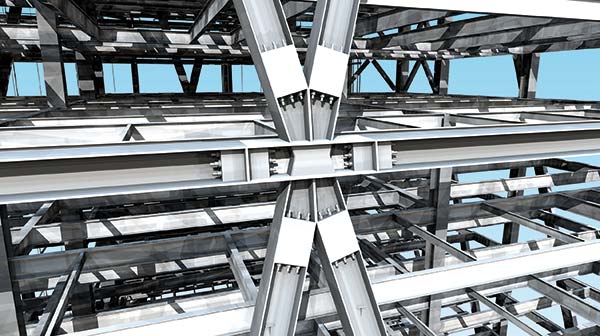 There are 11 different types of nodes with each type having various sub-variants according to the forces passing through the joint. Most nodes accommodate six members, although some have up to eight steel sections to connect.
Using prefabricated nodes has eliminated the need for any complex onsite welding as all of the challenging work was completed at Severfield- Watson’s facility. Even so, some nodes took up to 600 man hours to fabricate.
Alex Harper, Severfield-Watson Structures’ Project Director, says: “The nodes were delivered to site as complete pieces and then bolted into place, this was made complex by the massive scale of the components and the bolts together with the difficult access. However, using large prefabricated pieces with bolted splices was a quick and efficient method.”
The nodes’ bolts are high strength, threaded pre-tensioned bars up to 76mm in diameter. The connections are made within the profile of the members and transfer their pre stress to the members’ ends via plated bolt boxes situated between the flanges of the main steelwork beams and columns.
North Core
 Distinguishable by its yellow painted steelwork, the north core structure contains the passenger lifts, toilets and most of the service risers as well as onfloor plant in a slender frame which connects back to the main mega frame on every floor level.
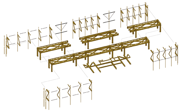
For speed and ease of construction most of the components for the core were prefabricated into ‘tables’, three for each level.
Steelwork for each ‘table ‘ consists of a floor level and attached columns. Once on site the tables were craned into position and fitted together like Lego bricks.
To speed up the construction programme the tables consisted of much more than just steelwork “Once fabricated they were transported to one of our factories where they were fitted with primary M&E components and precast concrete floors,” explains Andy Butler, Laing O’Rourke Project Director. “Each table then weighed 40t when it arrived on site to be lifted into place.
“This eliminated the need for many follow on trades to work at height later in the programme.”
On the north elevation, the primary beams, columns and cladding of the core form a backdrop to the 20 passenger lifts and two goods lifts, which travel up to 200m-high within cantilevered suspended glass shafts.
The use of nodes in the Leadenhall Building
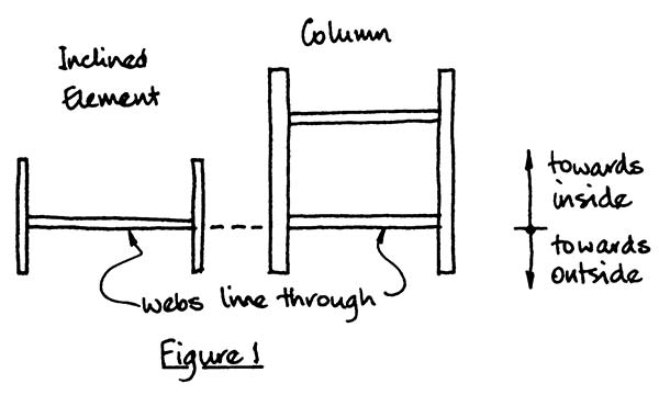
 The arrangement of the nodes is driven by the basic geometry of the frame (the width of the members and the angles between them) and by the architectural requirement to make the connections within the envelope of the members. Some of the heaviest columns are in the tapering side elevation where the columns extend over the full-height of the building and carry over 50 MN. These elements are in section a box with inset webs. The inclined members, some of which are in tension because of the massing of the building, carry much lighter loads than the vertical members. They are an I section with the web plate aligned with the outer web of the column (See figure 1).
 Within the nodes the web plate is effectively a continuous plate. Out of plane forces at changes in direction of the flanges are carried by stiffeners and cover plates welded to the toes of the flanges. These also form the bolt boxes at the ends of the legs of the nodes.
 The mega frame is designed as rigid-jointed and, to assure the columns have continuity of stiffness through the joint, the mating faces of the end-plates are required always to be in positive contact over their full area. Thus, there is no reduction of stiffness under applied bending moment as a result of loss of contact over part of the end plate due to opening of the joint. The end plates are machined to ensure the surfaces mate effectively. Bolts were tensioned simultaneously using hydraulic bolt tensioners. The bolts are Grade 10.9 bars threaded at each end with a maximum tension in some of 2MN.
The joints were checked by producing an interaction diagram for biaxial moment and axial force similar to that for a concrete column. For the given bolt pre-stress, points representing any design combination of axial force and bending moments were shown always to lie inside the “failure” envelope, indicating no joint opening would occur.
To remove the shims in the active alignment process, the joint in an inclined element was opened by slackening off the bolts, or by jacking apart where the element was in compression. In this case, two pairs of angles were bolted to the inclined column on either side of the mating end plates. Four jacks were positioned between the projecting angles outside the envelope of the members. When the force between the mating surfaces was relieved, comb packs could be removed to shorten the member by the required amount.
Dr Richard Henderson (SCI)