Projects and Features
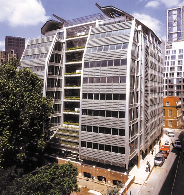
Beaufort Court, Lillie Road, London

Fig 1: Finished building
Following its successful use of volumetric modules in two housing schemes in London, the Peabody Trust now has a project under construction that combines the use of light gauge steel panels, volumetric bathroom units and hot rolled steel elements. Michael Eatherley and Nirupa Perera report.
FACT FILE: Beaufort Court, Lillie Road, London
Architect: Feilden Clegg Bradley Architects
Services consultant: Max Fordham & Partners
LGS contractor: Ayrshire Metal Products
Structural Engineer: Michael Barclay Partnership

Fig 2: Block A Core
The new housing development for the Peabody Trust is built on the site of a demolished school in Fulham, West London; it stands immediately adjacent to one of the Trust’s original estates with which it shares new social facilities.
The development is very much in line with the government’s housing agenda – a high density urban development with mixed tenure and provision for the socially excluded.
The development provides 65 housing units, a tenants’ meeting room and an underground car park for 44 vehicles. The mix of accommodation is complicated and has a significant effect on the structural arrangement:

Architectural design
The design solution consists of three blocks forming the north, south and east boundaries to a protected enclosure. The blocks are arranged around a raised landscaped courtyard that forms a focus for the site and sits above a semi-basement car park.

Fig 3: Site Plan
The three blocks are treated individually according to their locations on the site, type of accommodation and relationship to surrounding buildings and boundaries. Block A on Lillie Road has six storeys giving it the same overall height as the earlier Peabody buildings to the west. Block C on the east boundary sits above the car park and has three storeys above the deck. All of the flats have private balconies. Block B is a terrace of two storey houses with long private gardens to the rear (fig.3).
The external façade of the buildings consists of a pattern of full height glazing, stack bonded terracotta blocks, terracotta rainscreen cladding and coloured render. The arrangement is punctuated with visually expressed steel columns, beams and balconies. The lower blocks have green roofs planted with sedum, which reinforce the green landscape strategy.
Services
The houses have individual heating systems, each with its own boiler, while the flats all use electrical storage heaters. Services are fully integrated into the structure. The most challenging feature was the arrangement of the bathroom pods where the services to the bathroom including ventilation ducts were preset into the narrow duct at the side and then fitted together on site without disturbing the bathroom finishes. One of the reasons for the prototype pods was to test the viability of adopting this procedure. It is expected that the building will surpass current best practice for energy efficiency.
Construction innovation and choice of structure
The aim was to follow best practice in relation to sustainable development and to adopt new ideas in construction where a benefit could be shown. In particular Peabody Trust wanted to promote the ideas emanating from the Rethinking Construction Programme and the Housing Forum.
An example of this is the way in which the team was integrated with the client entering into a partnering relationship with the constructor, key sub-contractors and the design consultants, using the Project Partnering Contract 2000. The process was open and transparent and resulted in a high degree of co-operation and trust being engendered between members of the team.
Another key recommendation in Rethinking Construction is to introduce a significant proportion of offsite fabrication. This too was promoted from the outset. In fact the architect adopted a structural crosswall grid of 4.2 metres early in the design development on the basis that it would permit, among other things, large volumetric construction.
Three forms of construction were investigated: conventional masonry cross walls with precast concrete floor planks, large room-size volumetric units in steel or timber, and finally light gauge steel wall and floor panel construction. The early analysis of the options suggested all to be feasible, with little difference in cost but with the two prefabricated types offering significant benefits in other areas.
The choice between volumetric and panel form was governed partially by Peabody’s wish to explore an alternative approach to the contemporaneous volumetric design for their Raine’s Dairy scheme in Stoke Newington. The other reason for favouring panels was the flexibility in design that they offered bearing in mind the complex pattern emerging from the planning restrictions and the particular mix of accommodation.
The structural approach: a hybrid system

Fig 4: Cutaway computer model showing LGS, Modules & façade structure at core
The structure devised is a prefabricated steel system incorporating large light gauge steel panels for floors and walls, three-dimensional modules for the bathrooms and hot rolled steel for balconies and other “visually expressed” steel components.
External walls are highly insulated; internal walls and floors provide excellent sound insulation (fig. 4). The system has a number of advantages in terms of environmental, economic, constructional and health and safety impacts. Some of these are:
- Prefabrication can result in significant environmental benefits by reducing waste and minimising pollution and by carrying out the work under controlled conditions
- The hybrid arrangement allows for a bespoke construction giving a high level of flexibility in architectural form
- Hot-rolled steel elements are incorporated into the structural system at key points in the elevations providing additional design flexibility, permitting large window openings and extensive balconies
- The use of light gauge steel tends to minimise transportation costs (both direct and environmental) and difficulties of site access.
- Fully fitted, three-dimensional construction is used for bathrooms, which are high value- added building elements
- The achievement of high construction quality
- High levels of insulation result in low energy consumption
- Low weight of construction results in economies in foundations and transfer structures
- Floor panels are pre-decked to provide safe working platforms during erection
- The site work is predominantly dry and clean – dry floor construction, dry-lining to the walls, much of the cladding is clipped in place and factory-made bathrooms. The result is high quality of construction and minimum wastage of materials
- The method permits a substantial saving in the programme of construction time
- The structure can be dismantled and a high proportion recycled at the end of its life
Substructure and ground floors

Fig 5: Erection of bathroom module
Ground conditions: made ground (including numerous old footings) to depths which vary from 1.2m about 2.5m; flood plain gravel to depths between 6.6m and 9.8m; London Clay to a depth in excess of 20m. No water was encountered.
Foundations: mass concrete trench fill foundations down to the sand or gravel formation were adopted throughout. (Piling would almost certainly have been required had the heavier conventional construction been adopted).
Ground floors: suspended reinforced concrete slabs with a power floated finish were adopted. Insulation was placed under the slab.
Car park: reinforced concrete to the basement slab and walls with steel beams and internal columns to support the deck structure. Asymmetric hot rolled steel beams were used acting compositely with precast concrete planks to form the deck.
Superstructures
Walls: braced light gauge steel panels, generally one storey high and up to 8m long with 100mm deep light gauge steel studs set at a spacing of 600mm. The studs are single at the upper levels and doubled back-to-back at the bottom. Party walls are in pairs to provide acoustic separation. Some of the walls are reinforced within their thickness at key points by hot rolled steel columns in order to support parts of the façade and cantilevering external balconies. At the preference of the lift supplier, hot rolled steel sections were also incorporated as frames for the three lift shafts.
Floors: light gauge steel floor cassettes usually about approximately 4.1m by 3m in size with the first layer of decking was screwed and glued in place in the factory. Floor studs are 250mm deep lipped C-sections (150 deep to terraces) set at 600 mm to coincide with the wall studs. In all cases, with the exception of the roof, construction is “balloon frame” meaning that the floors frame into the sides of the walls, allowing the walls to be contiguous. The alternative “platform” construction would require considerable stiffening to the ends of the floor studs and cause rather more difficulty in meeting the disproportionate collapse criteria in the six storey building.
Bathrooms: generally light gauge steel pods designed as integral parts of the structure. Their size is designed to fall within normal vehicular load restrictions to an inner London site. One fully fitted out pod and one fitted with the services were constructed in advance as prototypes and later incorporated into the structure.
Structural design
Load paths: Vertical loads are carried to the ground by cross walls at 4.2m intervals, except in the special cases of the core areas, which comprise lift shaft and stairs and an open “atrium” area.
Stability and holding down: North-south: by fully cross-braced cross walls with the floors acting as diaphragms.
East-west: by bracing in the spine wall at the east end coupled with the braced lift core modules. The building’s own weight means that in most cases there was no net uplift at the ends of walls and nominal holding down arrangements were necessary. Only in some of the walls at the east end were special connections introduced to hold the walls down to the foundations.
Thermal movements
The external steelwork is designed to move independently of the internal structure to allow for differential temperatures. To ensure longevity, sliding connections are in the form of stainless steel stud bolts in contact with stainless plates and slotted holes. Disproportionate collapse The general approach is to provide vertical and lateral ties to all the structural components or elements. Because the structural elements are closely spaced these loads may be reduced from the values given in BS 5950: Part 1. The guidance followed was that offered by the Steel Construction Institute Publication P301, but modified to account for a local concentration of load at the cores and at the key locations. In these instances higher loads are resisted by special ties.
As a further demonstration of the robustness inherent in this method of construction, we considered the effect of removing portions of the bottom storey of load bearing cross walls. It was clear that, even if the contribution of the plasterboard is ignored, the structure would not collapse and that local deflections would be limited to about 20mm. In reality the plasterboard would further limit the effect. This conclusion seems to be borne out by fullscale tests carried out a few years ago on a building with a similar form of construction.
Structural analysis and light gauge steel member design

Fig 6: Erection of floor panel
General: Light gauge steel (LGS) structural sections are formed from thin galvanised steel strip by a cold rolling process and are inevitably classed as slender. Consequently local buckling is an important consideration in design. Careful detailing and close attention to tolerances become particularly important. The sections were supplied by Ayrshire Metal Products from its standard range with thickness of between 1.15 and 2.4mm.
Walls: The vertical structures are a set of interconnected braced frames. Each structural frame was analysed under the usual combinations of dead, live, wind and disproportionate collapse loads to obtain the forces in the individual stud members. In Block A the cross walls are evenly distributed along the building, but in the long direction most of the stiffness is concentrated at the east end. The distribution of lateral forces in the longitudinal walls was found by a threedimensional analysis of the building that took account of the location and stiffness of each wall.
Having obtained the basic load in any wall stud, secondary bending effects were considered – wind on external walls, eccentric loads from floors, and an allowance for the effect of misalignment of studs above. The studs were then checked for combined axial and bending loads in accordance with BS 5950: Part 5 using our in-house stud design programme (note 1).
Floors: As well as the usual strength and serviceability conditions, dynamic behaviour was considered following guidance published by the SCI. In most cases the dynamic criteria governed.

Fig 7: Block A Core showing modules in foreground
LGS fabrication: The panels were made in Ayrshire. Component parts, studs, edge tracks or rimmers and noggins are rolled and cut to length before being assembled into flat panels in special adaptable jigs. Flat strip diagonal bracing to wall panels is applied to one face. Connections are by TIG welding to specified lengths. Tolerances of +/- 2 mm were achieved in the finished panels (note1).
Erection: Littlehampton Welding Ltd was responsible for the fabrication of all the hot rolled steel and the erection of the frame as a whole. The agreed sequence for the long Blocks A and C was to work from one end, completing a third at a time so as to enable the following trades to proceed. The general rule was to work from the middle outwards starting with the cores and with the internal hot rolled elements fully integrated into the procedure. Connections between LGS panels and between LGS panels and hot rolled steel are by self-drilling screws. The external or “expressed” steel connections incorporated sheets of fabric for sticking to the general breathable membrane which forms part of the weathering system to the facades. These members were installed “loose” so to avoid disrupting the scaffolding but to allow fine adjustment to match the terracotta rainscreens.
The first stage of erection provided a valuable learning period in fine tuning sequences and getting to grips with the levels of accuracy required. Subsequent stages became increasingly straight-forward and early delays were made good.
The project was completed in July 2003 to time and to the budget of just under £7.5m.
Michael Eatherley and Nirupa Perera are partners of Michael Barclay Partnership.
The project received an award for unbuilt projects in the 2001 Housing Design Awards.
Footnote (1): Stud design programme The user chooses from a library of stored geometry of many of the common available sections as both single and double combinations, selects the grade of steel, selects the effective lengths for the two axes, inputs axial force, bending moments about each axis and shear force. The programme then calculates the effective properties of the section and checks each of the acceptance criteria to the BS including a warning check on deflection assuming an uniformly distributed load.