Projects and Features
BBC at the Mailbox in Birmingham
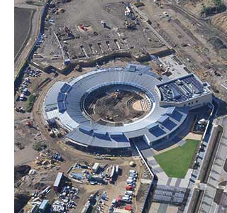
A redundant postal sorting office building has been converted into a retail and office centre called The Mailbox. The BBC has established a studio building within it, which required very thin suspended mezzanine floors.
Architect BDP
Structural Engineer BDP
Steelwork Contractor Fabsec
The BBC at the Mailbox, Birmingham is developed within a 72m x 72m double height floor, and a second double height space beneath, approximately a quarter of this size in plan. The design objective was to create a state-of-theart broadcasting facility, while providing a modern and effective operating environment for staff, and opening up the space to the license payer, so that the facility would become a showcase for BBC creativity.
THE PROJECT
At the heart of the area is a dramatic public entrance space, rising through two double-height floors, and fronting onto the Mailbox’s retail ‘street’. At the lower level, edit suites and studios are located, including specialist acoustic boxes. On the higher existing floor, additional technical areas are provided including drama and TV studios, from which open plan space extends. This office accommodation is arranged over two levels, the higher level formed of steel lattice structures known as ‘gondolas’.
The ‘gondolas’ themselves are conceived as accommodation floors and as service spines delivering fresh air, power, data and communications into the office areas. The structural concept uses aircraft wing technology where services are integrated into the supporting structure and the skin contributes to the stability.
Externally, the existing façade has been modified to increase the areas of glazing and to provide a major picture window on the south-west elevation. This new window overlooking the canal is designed to both ‘sign’ the BBC presence in the Mailbox and also, with solar shading, to provide an open aspect to the south-west. It improves both the quality of internal natural light and reinforces the visual link to the public canal-side space.
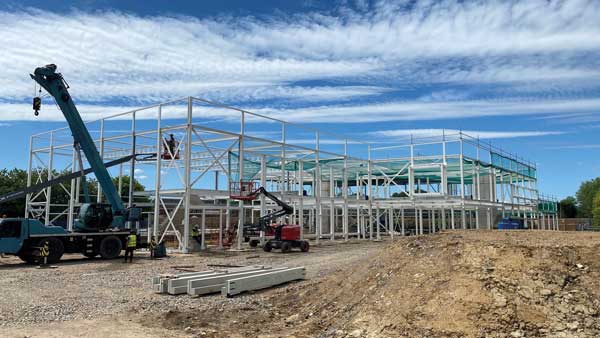
EXISTING FRAME
The original Mailbox building was constructed in the late 1960’s. It has a steel frame superstructure supporting pre-cast concrete floors. The basement and sub-basement are of in-situ concrete construction. The structure is generally set out on a 12.1m x 12.1m (40 feet) module with grid changes local to cores. The vertical cores on the perimeter and within the floor plate have concrete walls and braced steel bays and provide the structural stability of the building.
 THE “GONDOLAS”
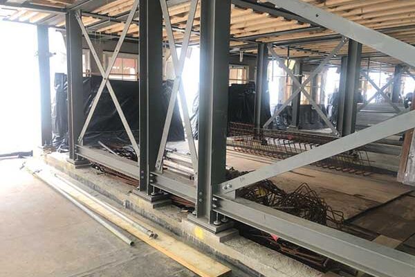
The existing floor-to-floor height of the structure is 6m. The “gondolas” are placed at mid-height, bringing the new floor-to-floor height to 3m. The reduced headroom generated a tight fit design solution integrating the structure, the primary and secondary distribution runs of the building services, the ceilings and raised floor support. The complete system had to fit in a 410mm zone. A bespoke floor structure was designed, using the full available depth for the structure and with large holes in the floor beam webs to accommodate the service runs.
The gondola floor structure is a 2-way spanning grid. The deck is suspended from high-level collar connections at the top of the adjacent steel columns, allowing the floor to float free of the column grid. The suspension system consists of Macalloy bars that pick up the ends of the primary beams. These hangers break the 12m clear spans and are required to ensure the floor achieves an adequate natural frequency value.
Each beam was specifically designed for its function. The primary beams are 410mm deep steel beams on a 3m grid. They span 10.2m across the floor and are tapered at the ends. The secondary beams are in the same horizontal plane as the primary beams and are 410mm deep, on a 1.8m grid, and bolted to the primary beams. The bolted connections are designed to resist moments and ensure the continuity of the secondary beams.

Computer generated view of building – graphic: Naish Waddington Architects.
Holes approximately 1000mm x 260mm are provided through the webs of the beams at predetermined positions to accommodate the service distribution. They are generally at 1800mm spacing. A secondary, cold-formed structure is located on the bottom flange of the secondary beams and provides support to the pedestals of the raised floor and a plywood crash deck to provide a secure deck below the raised floor for construction and future maintenance.
Crossbracing flat bars located below the top flange of the primary beams provide the structural stability of the gondolas.
Lightweight bridges link the three sections of gondola floor. They are suspended from the primary and secondary steel structure directly above. All exposed steelwork is finished in sprayed micacious iron oxide paint.
The limited headroom and tight fit design meant that the allowable fabrication and erection tolerances were limited. The beams were fabricated with a pre-camber to remove the dead load deflection. A special regime was established to monitor the tolerances from fabrication to the various stages of erection, to prevent the accumulation of tolerances detrimental to the scheme.
FLOOR VIBRATION
It was acknowledged very early in the design process that the limited floor depth available and the relatively long floor spans would make the dynamic behaviour of the floors the governing criteria in the design of the gondolas.
Limited guidance exists on the vibration design of non-conventional floors. We have conformed to the guideline recommendations where they exist, in particular, those provided by the Steel Construction Institute’s Design Guide on the Vibration of Floors. Also, we applied our in-house experience to extrapolate these guidelines to inform the design of the mezzanines.
We have set the acceptance criteria for the new floors, in accordance with the guidelines, to those for ‘general office’ use. These criteria are:
- recommended minimum natural frequency: 4Hz
- recommended maximum response factor, BS 6472: 8
The perception of floor liveliness will very much depend upon the exact positions of furniture and partitions and the random dynamic loading patterns emerging from usage. It was necessary to imagine realistic load combinations and configurations in assessing the structural dynamics of the proposed structure. Tuned mass dampers had been designed as a fallback solution, in case the mezzanines proved too lively.
A first portion of the mezzanine floor was erected in-situ as a prototype, to verify the detail assemblage of the structural, service and architectural components. In particular, the sequence of construction was critical in order to ensure the hangers were tensioned to satisfactory levels. The prototype was also used as a testing platform to measure its natural frequency and response factors under various live load conditions and the full accumulation of the fabrication and erection tolerances. The prototype allowed the client and the designers to review the performance of the mezzanines prior to proceeding with full production. The main contractor and the steelwork contractor also used the prototype to finalise their method statements and sequencing.
Measurements were carried out by the BRE. Under full dead and live load, the BRE measured displacements at fixed positions, the tension in the hangers and the natural frequency of the system. The measured results matched the anticipated values, predicted through calculations and modelling. The overall response of the mezzanine was considered adequate and the tuned mass dampers were not added to the design.
Michelle McDowell and JP Cartz are Directors of BDP Structural Engineering