Projects and Features
Better Practice in Steel Design
David Brown offers encouragement with common design issues deserving attention.
SCI courses offer an opportunity for design engineers to get to grips with the theory and practice of steel design. They also provide an excellent opportunity for SCI staff to appreciate the common concerns that practising designers experience. It is all too easy for SCI staff to think that because a subject has been covered in a guide, the objective has been met, that all designers now understand and are following the advice. Meeting designers on courses and dealing with their very real questions on the advisory line helps us keep some degree of reality in our thinking, and is a useful barometer for how well issues are understood. This article covers no new ground, but, based on our interaction with designers, it covers issues that deserve further explanation.
CHOICE OF STEEL SUB-GRADE
We all appreciate that most materials become less ductile at lower temperatures. I recall seeing a Mars bar being flexed at room temperature, but after immersion in liquid nitrogen being spectacularly shattered with a hammer. Many DIY enthusiasts will be aware of breaking cast iron drainpipes into transportable pieces not with a saw but with a sledgehammer – since cast iron is a brittle material.
The same principles apply to structural steel, and the design Standard BS 5950-1 requires that material sub-grades (i.e. “grades” and “qualitites” to use the terms from the material Standard EN 10025 are chosen to ensure adequate lowtemperature ductility or “toughness”. The need for tougher material increases:
- as the tensile stress increases,
- as the temperature decreases,
- as the strain rate increases,
- with local stress raisers from non-uniform stresses, or potential crack propagators,
- with the likelihood of incipient cracks in the material microstructure,
- with thickness.
The more of the above that are present, the more likely brittle fracture, and a tougher steel-subgrade is required. BS 5950-1 directs the designer to Table 3, which addresses the type of detail, stress level and strain rate in which the steel is to be used.
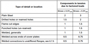
This is part of Table 3 from BS 5950-1:2000 Examples of factor K for type of detail, stress level (a low K indicates more onerous conditions)
The toughness of the steel sub-grade is characterised by its Charpy Value number (CVN). Charpy tests measure absorbed energy (in Joules) when a sample of material is broken, and are carried out at particular temperatures, since toughness varies with temperature. A high Charpy Value measured at a low temperature indicates a tougher steel. Tables 4 and 5 of BS 5950 indicate the maximum thickness of steel that may be used, depending on sub-grade and service temperature.
The designer’s obligation is therefore to study Table 3, (shown in part adjacent) and identify the factors that affect the steel, and then, knowing the thickness of the steel sections that have already been chosen and the service temperature, choose an appropriate sub-grade.
What goes wrong?
We are aware that in many cases, the steel subgrade is not specified. In some cases, it is assumed that the steelwork contractor will choose the sub-grade. However, although the steelwork contractor could guess, it is only the structural designer that really knows the state of stress, strain rate, service temperature etc. It naturally falls to the structural designer then, to specify the steel sub-grade.
Where to get further advice
Example calculation of steel sub-grade: SCI’s ‘Blue Book’ Volume 2 Worked Examples.
Further Information: Advisory Desk note 250 New Steel Construction Vol. 9 No. 5 Sept/Oct 2001.*
SWAY STABILITY
The good news is that more designers are checking sway stability. Until everyone is doing so, some frames may be experiencing second order effects that have not been allowed for. The main excitement is probably with braced frames, where past practice was simply not to check frame stability, assuming the frame to be non-sway. The key advice is to check sway stability, but not to be dismayed if the frame is classed as sway-sensitive. The approximate methods in the Standard to allow for the second order effects are in fact delightfully simple, and should not put anyone off. In many cases, the sway effects in a braced frame merely need to be amplified, typically by 15% maximum. This is simple and cost effective, compared to the alternative of increasing the bracing members in size until the frame is forced to be non-sway. For the enthusiasts with time to spare, it should be noted that frame stability is loadcase dependant, and advantage can be gained by assessing each loadcase.
Where to get further advice
Example calculation of frame stability: SCI’s ‘Blue Book’ Volume 2 Worked Examples.
Further details: “Multi-storey frame design”, New Steel Construction Vol. 10 No. 6 Nov/Dec 2002 and “Unbraced frames – sway stability”, Vol. 11 No. 3 May/June 2003.*
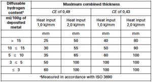
This is Table C1 from BS EN 1011-2:2001 Examples of maximum combined thickness weldable without preheat
WELDING PROCEDURES
Having made efforts to ensure our steel is suitably tough to avoid brittle fracture, there is a further consideration that affects material specification when considering welding. Absorbed hydrogen can lead to brittle failure in the heat affected zone (the small zone immediately adjacent to the weld metal). Welding Procedures (properly called Welding Procedure Specifications, or WPS) are prepared and tested to ensure that this hazard is avoided. Increasingly costly and inconvenient measures must be taken to avoid brittle fracture when welding thick material, and if the steel is susceptible. The procedures then should be appropriate for the thickness of the material joined, and also the susceptibility of the steel to hydrogen embrittlement. The susceptibility of the steel relates to the CEV. Table 1, taken from BS EN 1011, shows the balance between hydrogen, heat input, combined thickness and CEV. Note that as the CEV reduces, the allowable thickness increases as the steel becomes more “weldable” and less susceptible to cracking. Note also that with a given thickness, there are a number of appropriate solutions depending on the CEV, heat input and hydrogen scale – there is no single procedure for a particular circumstance.
What goes wrong?
Occasionally, the CEV of the steel is unknown, with the possibility that the WPS is inappropriate. The possibility that the WPS is not appropriate is more likely with thicker joints, where more elaborate procedures are usually required in any case. The maximum CEV is given by the material Standard, but this is usually higher than the actual CEV. WPS based on the maximum CEV are likely to be more involved (and costly) than those based on the actual CEV.
What should happen?
The CEV of the steel should be checked, and the WPS demonstrated to be appropriate for the steel and for the thickness of the material being welded. This accords with the National Structural Steelwork Specification (NSSS) which requires that this information is available. In Table 2.1 of the NSSS, note (2) states that “If the steel is to incorporate welded connections, ‘Option 5’ must be ordered”. Ordering of Option 5 relates to the product standard, and ensures that the CEV can be determined. Almost all steel structures incorporate welding, and the requirement to know the CEV is thus widespread. In clause 5.3.1, the NSSS insists that WPS are prepared following ‘the guidance of BS EN 1011-2 …to avoid hydrogen cracking’. The CEV is an essential piece of data required in following the guidance in BS EN 1011-2.
Thus, currently, option 5 should be the “default” basis for ordering structural steel. Revisions to EN 10025 currently planned will promote CEV from being an option to becoming mandatory. This provides the possibility to ensure that there will no longer be any potential mismatch between the WPS and the material specification.
Where to get further help
Welding lectures on www.steelbiz.org “Welding for Designers”;
New Steel Construction; Vol. 10, No. 5 Sept/Oct 2002.
TRUSS JOINT CAPACITIES
Common practice in general steel design is for the connection design and detail to be the responsibility of the steelwork contractor. This split responsibility works well for both nominally pinned connections in Simple construction and for rigid joints such as portal frame connections. A rather different policy must be adopted where the frame is semi-continuous, and so relies on very specific connection properties. In this case the structural designer must also specify the connection details.
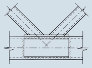
Truss joints that involve hollow sections, either as internal members or as chords, are an extreme example of where the normal practice of leaving the steelwork contractor to ‘design the connections’ is not appropriate. Once the layout (geometry) of the truss has been set by the designer, and members chosen, the joint capacity has been set, since this depends entirely on members, forces and geometry. Since the steelwork contractor is generally not at liberty to change the members, forces or geometry, his responsibility is to check the joint capacity, and if this is insufficient, to strengthen the joint by the addition of plates, often as shown in Figure 1. This is time consuming and expensive.
What goes wrong?
Simply that the joint capacities are not checked during the design process, often leading to expensive strengthening.
What should happen?
Best practice is that the truss designer calculates the joint capacities at the design stage, when the geometry might be modified, or different members chosen, so that expensive fabrication can be avoided.
Where to get more help
Design of SHS welded joints from http://www.corustubes.com/
BASE STIFFNESS
Accounting for base stiffness in analysis can be of significant benefit, even when the bases are nominally pinned, yet much confusion surrounds the subject. This is despite Advisory Desk articles in this journal, and specific clauses in BS 5950. In an attempt to encourage designers to use the beneficial stiffness of nominally pinned bases, the following is recommended when the bases are nominally pinned:
- Use 10% of the column stiffness as a base stiffness when checking frame stability. The stiffness of the base will improve frame stability, and is therefore beneficial. The effect of the base stiffness will be to reduce any amplification that is necessary, and will in some cases result in a frame being classified as non-sway, rather than sway-sensitive.
- Use 20% of the column stiffness as a base stiffness for SLS calculations. This will help reduce lateral deflections, often critical in the storey from ground to first floor if the bases are pinned.
- Assume a pin at the base when carrying out the ULS analysis and design. Use of any base stiffness at ULS will mean that both the baseplate detail and the foundation will need to be designed for the resulting moment – which is unwelcome in common UK practice.
Note that although points 1 and 2 above will, of course, imply moments at the bases, these can be ignored.
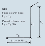
Modelling often causes confusion. A simple approach is to define a ‘dummy’ member that has either 10% or 20% of the inertia of the column section (depending on the check being considered). For simplicity, it is recommended that the extreme end of the dummy member is a pin, and therefore the length of the dummy member should be 75% of the length of the column, as shown in Figure 2.
What goes wrong?
The beneficial effects of bases stiffness, even with a nominally pinned base, are neglected.
Where to get more help
Modelling of steel structures for computer analysis, SCI. Available on www.steelbiz.org
Tables reproduced with the permission of BSI under licence number 2004SK/003. British Standards can be obtained from BSI Customer Services, 389 Chiswick High Road. London W4 4AL; (tel 020 8996 9001).
David Brown, Deputy Director of the Steel Construction Institute


