Projects and Features
Hull Stadium

Night photo from roof of Hull Royal infirmary
Hull City Council has built a multi-purpose stadium with a steel roof
CREDITS
Architect
(overall concept) Arup Associates
(detail design) The Miller Partnership
Structural Engineer Anthony Hunt Associates
Steelwork Contractors Watson Steel & Wescol
Steel tonnage 3,500 tonnes
In the late 1990s, Kingston-upon-Hull City Council floated Kingston Communications, the telephone company which gave Hull its distinctive cream coloured telephone boxes, on the stock exchange. It used part of the proceeds from this sale to fund an iconic stadium and community sports facility, which would act as a flagship regeneration project for the city.
On a freezing cold night in December 2002, Hull City FC played a friendly football match against Sunderland AFC in front of approximately 25,000 spectators, and the dream had become a reality. The stadium is now home to both Hull City FC (football) and Hull FC (rugby league) as well a community ‘Learning Zone’, a pioneering partnership set up by Hull City Council and Hull College. The complex also includes a 12-court sports hall, two all weather hockey pitches, a BMX/skateboard area and an aviary. The building has won several awards.

Main entrance to sports hall
SITE AND INFRASTRUCTURE
The stadium is in West Park, a 78-acre formal Victorian park located a short walk away from Hull city centre. However, the need to respect existing features within the park (including a significant number of mature trees) and the presence of several railway lines at part of the site boundary resulted in a surprisingly tight area within which the stadium had to be located. Significant civil engineering works were also required, including a major sewer diversion and an elevated walkway, which spans over a number of railway lines and brings pedestrians from the city centre.
ARCHITECTURAL CONCEPT
The architectural concept encompasses a number of features that are unique to UK stadium design, most notably the asymmetric bowl form that results from having single tier stands to the north, south and east sides and a two tier main stand to the west.

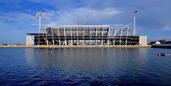
Arial veiw taken soon after completion
The bowl effect is enhanced by the roof line, which gently rises from its lowest point at the centre line of the single tier east stand to its apex at the centre line of the two tier West stand opposite, as well as by infilling the four corners. The roof-mounted wishbone floodlights at the south-east and north-east corners of the stadium also serve to give the stadium its identity, as well as preventing the west stand ‘A-frame’ roof structure from dominating the roofscape.
Other unique features include locating the main public concourse (which has been described as ‘cathedral like’) at first floor level, thereby freeing up commercially valuable space at ground floor level. Further space has been freed up by locating the four stair towers that serve the upper floors of the west stand outside the footprint of the stadium. This maximises the space available for public amenities and catering facilities, as well as enabling fans to walk fully around the stadium at events where segregation is not necessary, such as pop concerts.
STRUCTURAL DESIGN
From a structural point of view, the asymmetric bowl form of the stadium, with part single tier, part two tier, effectively results in ‘two stadia in one’. The junction between the single tier north, south and east stands and the two tier west stand is solved by gradually raising the roof level, as opposed to the normal solution of having a sudden vertical step in the roof line. This results in each half of the stadium being made of 36 frames, each one of which is different. In total, some 3,500 tons of steel was used in the construction of the stadium. Given the coastal nature of the site, the steelwork paint system had to take into account the corrosive nature of airborne salts.
SETTING OUT
The orientation of the stadium was partly determined by the need to minimise the wind uplift forces to the large overhang of the west stand roof. Consequently, the prevailing winds from the south west act on the rear elevation of the west stand.
The principal structural elements are all set out to a complex arrangement of plan curves, with different radii and setting-out points defining each element. This arrangement ensures good views from all seats, with no spectators having to stand in order to view the action in the corners (which is where much of the play occurs in a rugby match).
To assist construction, easting and northing coordinates were calculated for all critical elements, some of which were expressed as ‘global positioning system’ (GPS) co-ordinates.
NORTH, SOUTH AND EAST STANDS
The superstructure to the north, south and east stands is relatively straightforward. Steel frames at 7.5m centres support a single tier of precast concrete terracing that is accessed, via precast concrete vomitories, from the suspended composite slab and beam structure at lower concourse level. Overall stability is provided by a combination of frame action and bracing by the terracing raker beams. The 1.35m deep cellular roof beams cantilever up to 29m and are supported by two columns, one at the rear of the terracing and one along the external perimeter. Polycarbonate sheeting to the tips of the cantilevers maximises sunlight to the pitch edges and corners.

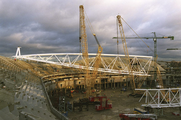
Erection of tubular steel A frames to west stand roof
WEST STAND SUPERSTRUCTURE
The superstructure to the west stand is similar in principle to that of the other stands, although it does have two tiers of terracing and four levels of suspended floor. In addition to frame action and bracing by the terracing raker beams (with additional vertical and plan bracing as required), overall stability is also provided by the stiffness of the 1.2m diameter concrete encased perimeter columns.
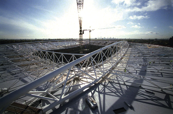
WEST STAND ROOF
The west stand roof is probably the most interesting aspect of the stadium from a structural point of view. Due to its significant overhang and the presence of the upper tier, the cantilever solution used for the other stands was not appropriate here. Consequently, a stayed rafter solution was adopted, using relatively slender 406mm diameter CHS stays to support box section rafters which are fabricated out of steel plate, and range from 1350mm deep at their supports, down to 600mm at the tip.
The CHS stays are up to 40m long, and rise gently in pairs up to the rear of the roof, where they meet six CHS section ‘A-frames’ which transfer the significant vertical and overturning forces down the stand, via terracing raker beams and diagonal bracing hidden within partition walls between hospitality boxes. To overcome potential problems associated with self-weight deflection and bending moments, the CHS stays were cranked at third points so that the deflected form approximates to a straight line.
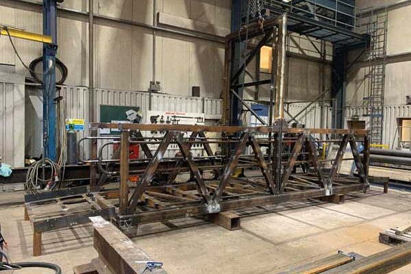
For reasons of transportation and buildability, the tubular A-frames were fabricated at the rear of the west stand and lifted into place as complete frames. This resulted in lifts of up to 110 tons that lasted eight hours in some cases. In order to minimise out of balance forces, the ‘A-frames’ were erected from the centre outwards. Hence, the two central ‘A-frames’ were erected first, and then joined together by erecting RHS infill purlins between them. This process was subsequently repeated for the two intermediate and the two outer ‘A-frames’, after which the roof decking could be laid. The west side of the pitch is lit from a dedicated lighting gantry slung off the underside of the west stand roof. Again, polycarbonate sheets at the front of the west stand roof maximise sunlight to the pitch.
DYNAMIC BEHAVIOUR
In addition to football and rugby, the stadium will be used for pop concerts. Hence, the dynamic performance of the structure was designed to comply with the recommendations of the newly published Interim Guidance report, produced by the IStructE/DTLR/DCMS working group. This essentially requires that empty stands have a lowest vertical natural frequency of at least 6Hz, provided that the structure can resist a horizontal load equal to 7.5% of the vertical imposed load, in addition to the wind loads specified in Part 2 of BS 6399. This should ensure that significant resonant excitation at the second harmonic frequency of crowd movement is avoided. A sophisticated 3-D computer model was initially created to determine the dynamic response of the structure, the results of which were subsequently evaluated against physical tests carried out on the as-built structure by Sheffield University’s Vibration Engineering Research Section. The practical implications of designing for pop concerts are essentially stiffer precast terracing units, stiffer steel terrace raker beams, and additional bracing (in both horizontal and vertical planes).
THERMAL MOVEMENT
The bowl arrangement of the stadium is such that the north, south, east and west stands are prevented from expanding towards (and contracting away from) the corner areas. Consequently, the superstructure is jointed using pairs of expansion joints at all four corners of the stadium.
PROGRAMME AND BUDGET
The main contractor was appointed in September 2001, when the detailed design began. The site works started one month later in October 2001, and the opening match was played just 14 months later in December 2002. The building was delivered both on time and within the client’s budget. The extremely tight programme was only achievable by establishing a close working relationship with the steelwork contractors at an early stage in the detailed design process. Indeed, the steelwork contractors made an invaluable contribution in terms of assisting with the connection design and advising on buildability.

Opening night – view from south-west corner
ONE YEAR ON
Since the stadium opened almost a year ago, Hull City FC and Hull FC have both seen significant increases in their attendance figures. Further, the stadium has been ‘sold out’ for a number of events including an England U21 friendly, an Elton John concert, and a rugby league test match between Great Britain and Australia. Indeed, the stadium has captured the imagination of the people of Hull as well as visitors to the city, many of whom believe the ‘spectator experience’ at the Kingston Communication Stadium is second to none.
Jon Carr, Associate at Anthony Hunt Associates