Technical
AD 461: Anchorage of bars in the troughs of composite slabs
Introduction
Traditional practice in the UK uses continuity over the supports, combined with a small contribution from the decking in the span, to provide composite slab hogging and sagging moment resistances that are sufficient to support the loads in a fire situation. Fire tests have validated such an approach. The hogging resistance is significant under fire conditions because the reinforcement (normally in the form of fabric mesh) in the upper part of the slab remains relatively cool and has a reasonable lever arm. The contribution of the decking is small because, acting as external reinforcement, it is directly exposed to the fire and so loses much of its strength. An apparent idiosyncrasy of this approach is that end continuity is normally ignored for ambient temperature design (although it is relatively much less significant in that condition).
When there is no physical continuity at the slab ends the sagging resistance alone will not be sufficient to resist loads in a fire unless bars are placed in the troughs to act as the lower layer of reinforcement, and ensure adequate sagging resistance. Because they are insulated through the provision of concrete cover they remain relatively cool and thus retain significant, if not full, strength. The provision of bars in the troughs is common practice across Europe for all composite slabs, a situation that is reflected in EN 1994-1-1 Annex D (an Informative Annex that is not adopted according to the UK National Annex).
Anchorage of reinforcing bars
Any reinforcing bar requires anchoring before it can resist a tensile force. Anchorage is typically, and most easily, achieved by having sufficient length of bar surrounded by concrete. Eurocode 2 gives rules for anchorage lengths. To ensure the most up-to-date information, although it is not yet publicly available the table below is taken from the latest draft of the ‘new’ prEN 1992-1-1. It is worth noting that anchorage lengths may be reduced when bars are subject to a lower level of stress.

The ‘new’ prEN 1992-1-2 says that the values given above are also applicable to fire conditions, and when there is no shear reinforcement (as is the case with a composite slab) anchorage lengths should be determined assuming poor bond condition, i.e. increased by 20% as per the note in the table above. However, we propose that this increase need not be applied in the case of composite slabs as it reflects the tendency of concrete to spall when an RC slab is exposed to fire, and the presence of decking prevents such spalling.
Example
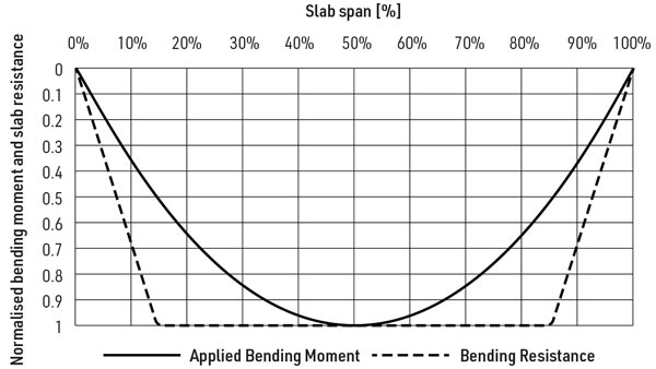
For a situation with a 12 mm bar (which is at the upper end of the typical range) in concrete with a characteristic strength of 35 N/mm² (also at the upper end of typical), using information from the table below left the anchorage length needed to achieve yielding of the bar is 12 × 36 = 432 mm. For a 3 m span slab the full strength of the bar could therefore be relied upon anywhere in the middle 70% of the span. For the 15% at either end the sagging resistance will build up linearly from zero at the support. This development of resistance (giving a tri-linear envelope) can be compared to the development of applied moment to see whether the bar anchorage will be adequate. For uniformly distributed loading the applied moment envelope is of course parabolic. The table below shows applied moment and moment resistance at certain distances from the support. The table shows that at only 5% of the way ‘into’ the span, say 150 mm, the bars would already have sufficient anchorage to generate over one-third of their resistance as ambient temperature, which is more than adequate to resist the applied moment. Values of applied moment and moment resistance are also plotted in the figure below, as a function of span.
Conclusion
For situations with uniform loading, or predominantly uniform loading, it can be concluded that straight bars with no extra provision for anchorage will be adequate. As with all composite elements, when the loading is heavily non-uniform, specific checks should be carried out using the principles given above. Resistance could be increased by using larger bars and/or increasing anchorage for example by forming the bar ends into hooks (if space allows).
Contact: SCI Advisory
Tel: 01344 636555
Email: advisory@steel-sci.com