
Technical
AD 374: Design of gusset plate connections
Following a failure, in 2012, of a relatively long gusset plate connection, the SCI has looked into the performance of the behaviour of gusset plates subject to compression. The interim results from this investigation show that for bolted gusset plates connected on one edge only subject to compression (shown in Fig 1) the modelling assumptions are particularly crucial.
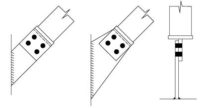
Fig 1: Gusset plates supported on one edge only
It should be noted that the advice given in the publication ‘Joints in steel construction – Simple Joints to Eurocode 3’ states:
‘Preferably, gusset plates in compression should be supported on two edges and be reasonable compact.’
‘Where the gusset plate is supported on one edge only, the detail is only recommended for light loads. For heavier loads, an extended end plate and gusset plate supported on two edges wherever possible is recommended.’
In the case of gusset plates as connections in a bracing system (which consists of a bracing member, spade end and gusset plate) the following issues may be important when deciding how to model the whole system:
- Is the connected bracing member stubby or slender and what are the implications for the likelihood of the gusset plate and spade end arrangements being subjected to a direct compression load (held in alignment by the stiffness of the brace) as opposed to bending from the brace moving out of alignment?
- Is the spade end on the brace itself stiffened (e.g. being made from an angle) or not?
- Even if the spade end on the brace itself is an unstiffened plate, is it relatively thicker, more compact and more securely welded than the gusset plate?
- Considering the bolt group connecting the gusset plate to the spade end of the brace, how effective is this in clamping the two elements together to restrain rotation?
- Considering the behaviour of the gusset plate itself, what is its likely mode of behaviour in terms of bending or buckling?
- Is the lapped connection to the gusset plate likely to fold with a hinge at each end of the connection?
As noted in the existing guidance for the gusset plate detail itself there are two specific issues to consider: - What effective length should be used?
- Is the actual or equivalent eccentricity of the applied load significant?
If the gusset plate is connected by a bolt group that provides good clamping action to a relatively stubby brace with a relatively stiff spade end, then the simple model assumed in the existing guidance may be appropriate, provided a suitably conservative value is chosen for the effective length. For a gusset plate connected on the skew it is not conservative to take the shortest distance between the last bolt row and the nearest weld attachment point.
The existing guidance shows the effective length to be the same as the system length for the gusset plate itself. In simple structural mechanical terms, this is equivalent to a model with the plate being assumed as fully restrained in position and direction at one end and being fully restrained in direction but not held in position at the other end.
In practice, a gusset plate supported on one edge would be welded all round at one end and clamped by the bolt group at its other end. If the clamping action of the bolt group is considered to provide only partial restraint in direction, then the effective length would need to be increased above the system length. In case of doubt, the conservative value for the effective length would be twice the system length for the gusset plate itself unless a small value can be justified.
In addition, the spade end on the brace itself may lack stiffness or the brace itself may exhibit curvature under load that results in an imposed bending moment on the plate. The effect of these would be equivalent to an eccentrically-applied load such that the simple assumption to ignore the eccentricity would be invalid.
The designer would need to consider the points above in deciding whether the simple model is appropriate. Some designers may have been tempted to use overlong single-sided gusset plates with minimum thickness without looking at the system modelling issues such as the behaviour of the brace, the behaviour of the spade end, the behaviour of the gusset plate and the interaction between these components and the effect this may have on the propensity of the gusset plate to bend or buckle.
Further guidance funded by BCSA and Tata Steel is on its way. In the meantime designers are reminded that the use of single-sided gusset plates should only be used for light loads and stiffened if necessary if a double sided attachment is not possible. The length of the gusset plate should be kept to a minimum and the effective length should be chosen on the most conservative basis. Furthermore, the effect of ignoring the eccentricity of the connected plates should be reviewed against the modelling assumptions for the behaviour of the whole bracing system.
Contact: Dr D. B. Moore, Director of Engineering BCSA
Tel: 0207 747 8122
Email: david.moore@steelconstruction.org


